
A non-contact induced current detection system and method based on lock-in amplification

An induction current, non-contact technology, applied in the direction of measuring current/voltage, measuring devices, measuring electrical variables, etc., can solve problems such as interference and errors, and achieve the effect of avoiding the introduction of errors and facilitating the recording of test data

Active Publication Date: 2022-01-11
ZHONGBEI UNIV
View PDF0 Cites 0 Cited by
  • Summary
  • Abstract
  • Description
  • Claims
  • Application Information

AI Technical Summary

Problems solved by technology

At present, there are many methods of current detection, such as temperature measurement, colorimetry, current sensor, etc., will cause interference to the unit under test due to their own work, thus introducing errors

Method used


Image

  • A non-contact induced current detection system and method based on lock-in amplification
  • A non-contact induced current detection system and method based on lock-in amplification
  • A non-contact induced current detection system and method based on lock-in amplification

Examples


Embodiment Construction

[0026] The following will clearly and completely describe the technical solutions in the embodiments of the present invention with reference to the accompanying drawings in the embodiments of the present invention. Obviously, the described embodiments are only some, not all, embodiments of the present invention. Based on the embodiments of the present invention, all other embodiments obtained by persons of ordinary skill in the art without making creative efforts belong to the protection scope of the present invention.

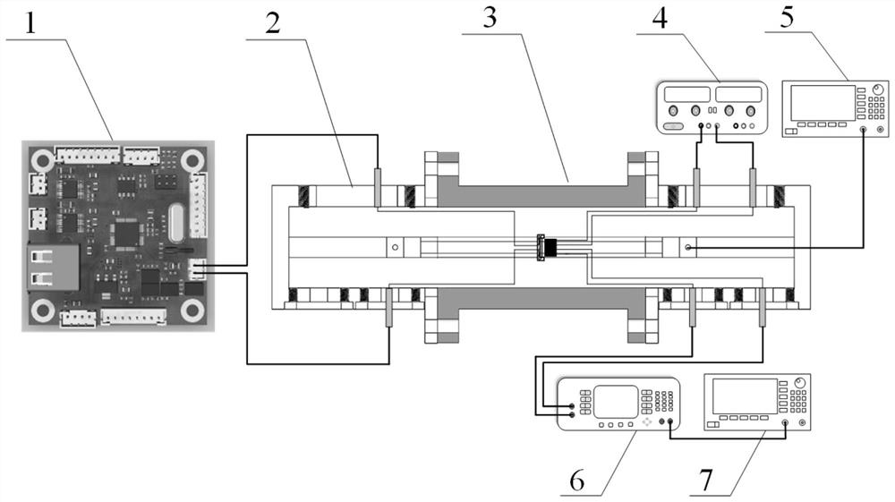
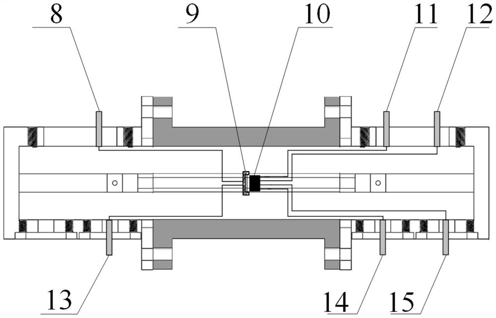
[0027] A non-contact induction current detection system based on lock-in amplification, such as figure 1 As shown, it includes a control circuit 1, a wave-to-wave converter 2, a double ridge waveguide 3, a power module 4, a first radio frequency signal source 5, a lock-in amplifier 6, a second radio frequency signal source 7, and two double ridge waveguide 3 Terminals are respectively connected with a wave-to-converter 2, and the double-ridge waveguide 3 is re...


PUM


Abstract

The invention belongs to the technical field of induction current detection, and specifically relates to a non-contact induction current detection system and method based on phase-locked amplification, including a control circuit, a wave-to-wave converter, a double-ridge waveguide, a power module, and a first radio frequency signal source , a lock-in amplifier, a second radio frequency signal source, two ends of the double ridge waveguide are respectively connected with a wave-to-wave converter, and the double-ridge waveguide is respectively connected to a control circuit, a power module, a first radio frequency signal source, A lock-in amplifier, the lock-in amplifier is connected with a second radio frequency signal source, a sensitive unit bridge wire and a tunnel magneto-resistance probe are arranged in the double ridge waveguide, and the sensitive unit bridge wire is connected with the tunnel magneto-resistance probe. The invention can effectively avoid the error introduced by the test equipment, and can extract the effective output voltage value of the tunnel reluctance probe in the interference environment through the phase locking method, thereby indirectly obtaining the magnitude of the induced current on the bridge wire of the sensitive unit. The invention is used for the detection of induced current.

Description

technical field [0001] The invention belongs to the technical field of induction current detection, and in particular relates to a non-contact induction current detection system and method based on phase-locked amplification. Background technique [0002] The magnetic sensor based on the tunnel magnetoresistance effect has many advantages such as high sensitivity and low power consumption, and has irreplaceable advantages in various fields. It can sense changes in physical quantities related to magnetic phenomena and convert them into electrical signals for output; In the environment, the change of the electromagnetic induction current will cause the change of the surrounding electric field. According to the law of electromagnetic induction, the changing electric field will produce a changing magnetic field. The tunnel magnetoresistive sensor is used to detect the changing magnetic field in the electromagnetic environment, so that the magnitude of the electromagnetic inductio...

Claims


Application Information

Patent Timeline
Patent Type & Authority Patents(China)
IPC IPC(8): G01R19/00
CPCG01R19/00
Inventor 王耀利黄晓龙吴倩楠王志斌李孟委
Owner ZHONGBEI UNIV
Learn More