
Distributed optical fiber monitoring pre-buried groove

A technology of distributed optical fiber and pre-buried grooves, which is applied in the direction of optical fiber/cable installation, fiber mechanical structure, etc., can solve the problems of not fixing and limiting the light, so as to improve work performance, facilitate limiting and fixing, and ensure The effect of normal transmission

Pending Publication Date: 2020-07-24
江苏亚冠轨道交通科技有限公司
View PDF0 Cites 0 Cited by
  • Summary
  • Abstract
  • Description
  • Claims
  • Application Information

AI Technical Summary

Problems solved by technology

[0005] To this end, the embodiment of the present invention provides a distributed optical fiber monitoring pre-embedded groove. Through the design of the fixing mechanism, the optical fiber can be limited by structures such as the first spring. At the same time, the design of the first spring makes the first spring in the When the optical fiber is limited and fixed, the force on the optical fiber is small and uniform, and the optical fiber will not be deformed because the bolt is pressed too tightly, which ensures the normal transmission of the internal signal of the optical fiber and avoids the failure of the light to be fixed and limited. In order to solve the problem that the optical fiber is easily affected by external interference and affect the propagation of the signal, when the embedded groove in the prior art is used, most of the optical fiber is directly placed inside the embedded groove, and the light is not controlled. Fixed and limited, resulting in the problem that the optical fiber is easily affected by the interference of the external environment and construction, which affects the propagation of the signal, thereby improving the working performance of the optical fiber in the entire life cycle

Method used


Image

  • Distributed optical fiber monitoring pre-buried groove
  • Distributed optical fiber monitoring pre-buried groove
  • Distributed optical fiber monitoring pre-buried groove

Examples


Embodiment 1

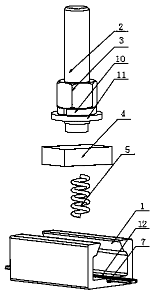
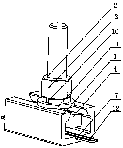
[0025] Refer to the attached Figure 1-2 , a distributed optical fiber monitoring cast-in groove according to this embodiment, comprising a cast-in groove body 1, a fixing mechanism is provided inside the cast-in groove body 1, and the fixing mechanism extends out of the top of the cast-in groove body 1;

[0026] The fixing mechanism includes a bolt 2, the bolt 2 is arranged on the top of the embedded groove body 1, the nut 3 is arranged outside the bolt 2, the nut 3 and the bolt 2 are connected by threads, and the bottom of the bolt 2 is provided with a limit Assemblies, the limiting assembly includes a fixed block 4, the top of the fixed block 4 is fixedly connected with the bottom of the bolt 2, the fixed block 4 is arranged inside the embedded groove body 1, and the bottom of the fixed block 4 is provided with a first spring 5. A T-shaped groove 7 is opened on the embedded groove body 1, and the T-shaped groove 7 is arranged at the bottom of the fixing block 4.

[0027] F...

Embodiment 2

[0033] The difference with embodiment 1 is:

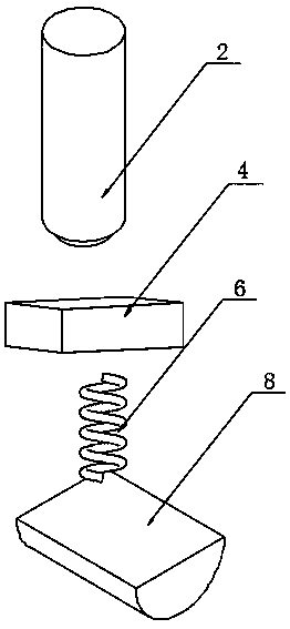
[0034] Refer to the attached Figure 3-4 , a distributed optical fiber monitoring embedded groove in this embodiment, the limit assembly includes a semi-cylindrical block 8, the top of the semi-cylindrical block 8 is fixedly connected to the bottom of the bolt 2, and the semi-cylindrical block 8 is arranged on the embedded Inside the tank body 1, the bottom of the semi-cylindrical block 8 is fixed with a second spring 6, and the embedded tank body 1 is provided with a semi-cylindrical groove 9, and the semi-cylindrical groove 9 is arranged at the bottom of the second spring 6 .

[0035] The specific implementation scenario is: when using the present invention, when there are few optical fibers 12 to be pre-embedded, if the optical fibers 12 are placed inside the T-shaped groove 7, since the space inside the T-shaped groove 7 is relatively larger, resulting in When the optical fiber 12 is pre-embedded, it is difficult to play a ro...


PUM


Abstract

The invention discloses a distributed optical fiber monitoring pre-buried groove, and particularly relates to the technical field of optical fiber pre-buried grooves. The distributed optical fiber monitoring pre-buried groove comprises a pre-buried groove body. A fixing mechanism is arranged inside the pre-buried groove body, and extends out of the top of the pre-buried groove body. The fixing mechanism comprises a bolt. The bolt is arranged on the top of the pre-buried groove body, a nut is arranged outside the bolt, and the nut is connected with the bolt through threads. According to the distributed optical fiber monitoring pre-buried groove, by means of the design of the fixing mechanism, an optical fiber can be limited through structures such as a first spring, when the first spring conducts pre-tensioning, limiting and fixing operation on the optical fiber, the stress of the optical fiber is small and uniform, the phenomenon that the optical fiber deforms due to the fact that thebolt too tightly presses the optical fiber can be avoided, the normal transmission of signals inside the optical fiber is guaranteed, the problems that due to the fact that the optical fiber is not fixed, the optical fiber is prone to being disturbed by the external environment and the construction, and signal transmission is affected are solved, and therefore the working performance of the optical fiber in the full life cycle is improved.

Description

technical field [0001] The invention relates to the technical field of optical fiber embedded grooves, in particular to a distributed optical fiber monitoring embedded groove. Background technique [0002] The dielectric waveguide that transmits light waves. The optical fiber is a kind of fiber composed of two layers of transparent media that form concentric circles. The most widely used dielectric material is quartz glass. The inner layer of the medium is called the core, and its refractive index is higher than that of the outer layer ( It is called the cladding), and the refractive index of the core or cladding is adjusted by doping germanium, phosphorus, fluorine, boron and other impurities in the quartz glass. The transmission wavelength of the optical fiber for communication is mainly near-infrared light with a wavelength of 0.8 to 1.7 microns. The core diameter of the optical fiber varies depending on the type, usually a few microns to 100 microns, and the outer diamet...

Claims


Application Information

Patent Timeline
Patent Type & Authority Applications(China)
IPC IPC(8): G02B6/44G02B6/46
CPCG02B6/44G02B6/46
Inventor 陈建荣
Owner 江苏亚冠轨道交通科技有限公司
Learn More