Position auxiliary beam alignment method and system based on multi-arm steal

A beam and bandit technology, applied in the field of beam alignment system, beam alignment, and position-assisted beam alignment based on multi-arm bandits, can solve the problem of high time complexity of beam scanning algorithm, complex implementation process, limited application range, etc. problem, achieve the effects of shortening the beam alignment time, improving spectral efficiency, and reducing the number of beam pairs

Inactive Publication Date: 2020-07-24
SHANGHAI RES CENT FOR WIRELESS COMM +1
View PDF10 Cites 6 Cited by
  • Summary
  • Abstract
  • Description
  • Claims
  • Application Information

AI Technical Summary

Problems solved by technology

However, each of the above algorithms has certain limitations.
For example, the time complexity of the beam scanning algorithm is relatively high, and the search efficiency is very low
The implementation process of AoA / AoD channel estimation algorithm, beam training optimization algorithm and side information auxiliary algorithm is very complicated, and the application range is relatively limited

Method used


Image

  • Position auxiliary beam alignment method and system based on multi-arm steal
  • Position auxiliary beam alignment method and system based on multi-arm steal
  • Position auxiliary beam alignment method and system based on multi-arm steal

Examples


no. 1 example

[0036] This embodiment introduces a specific scenario where the position-assisted beam alignment method provided by the present invention is applied to wireless communication.

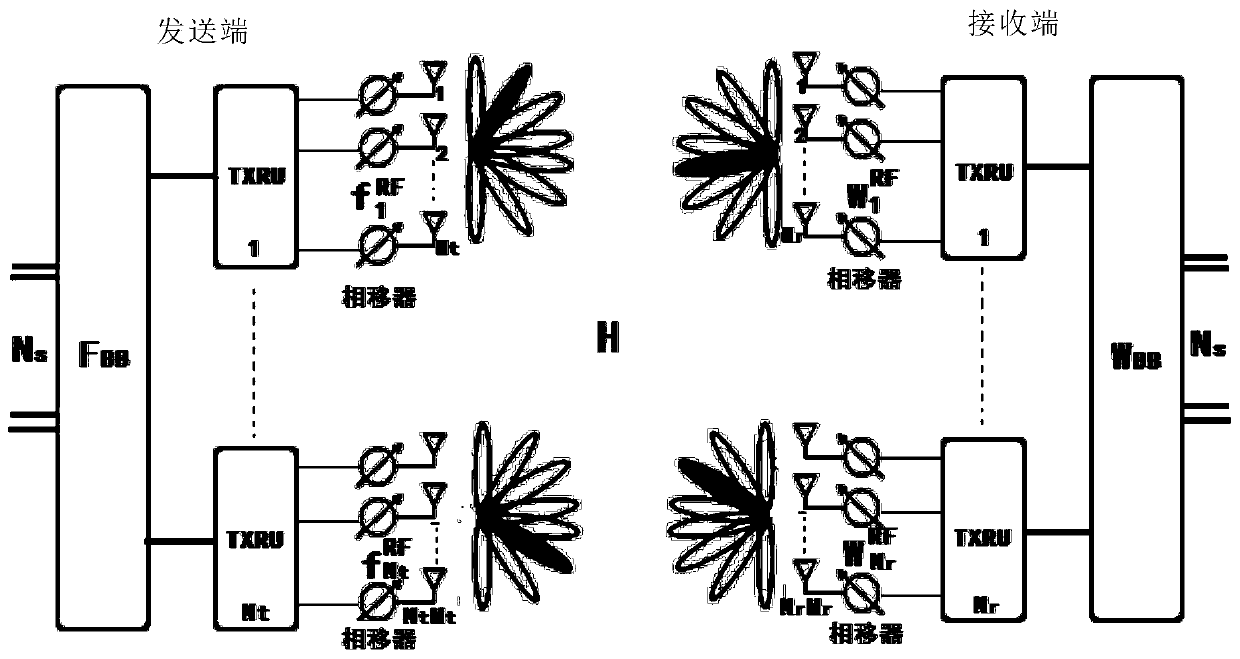
[0037] figure 1 A massive millimeter-wave MIMO system for implementing this position-assisted beamalignment method is shown. In one embodiment of the present invention, a uniform linear array (Uniform Linear Array, ULA for short) is selected. Among them, the uniform linear array of the base station 1 (abbreviated as BS) as the transmitter Tx is a uniform linear array with M t M with half-wavelength antenna spacing Tt The first uniform linear array of ×1 dimension; the uniform linear array of the user equipment (abbreviated as UE) as the receiver Rx has M r M with half-wavelength antenna spacing rR ×1-dimensional second uniform linear array. Such as figure 1 As shown, base station 1 end has N t RF links and N t × M t The first uniform linear array composed of root antennas. They are based on O...

no. 2 example

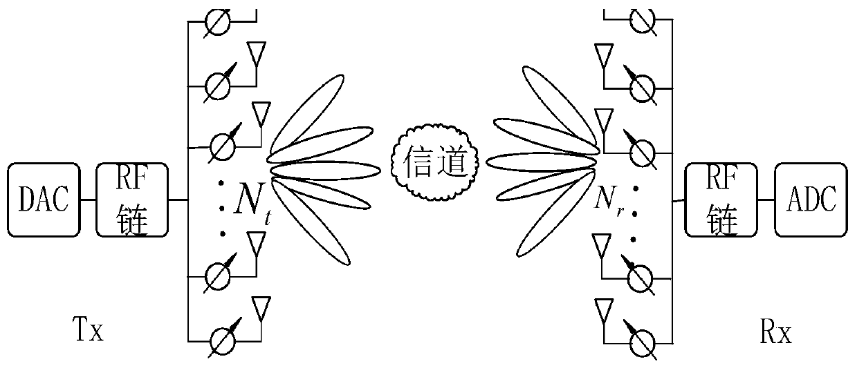
[0102] Such as image 3 As shown, the location-assisted beam alignment method provided by the present invention can be applied to the Internet of Vehicles. Among them, the transmitter Tx is installed on a first vehicle, and the receiver Rx is installed on another vehicle. The transmitter includes a DAC (digital-to-analog conversion) module, a radio frequency link, and a linear antenna array; the receiver includes an ADC (analog-to-digital conversion) module, a radio frequency link, and a linear antenna array.

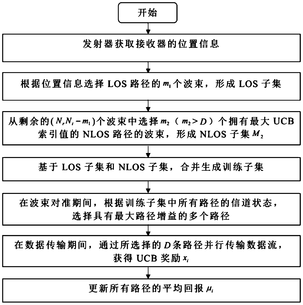
[0103] Such as Figure 4 As shown in , obtain the vehicle position information, select the corresponding line-of-sight path and the set of adjacent paths from all beam sets according to the vehicle position information; calculate the UCB of all remaining paths, and select multiple paths with the largest UCB to form the non-line-of-sight path distance path; measure the channel status of the line-of-sight path and the non-line-of-sight path, and select D paths with the ...


PUM


Abstract

The invention discloses a position auxiliary beam alignment method and system based on multi-arm steal. The method comprises the following steps: acquiring position information of a receiver; selecting a plurality of LOS beams of the LOS path according to the position information to form an LOS subset; selecting a plurality of NLOS beams of the NLOS path with the maximum UCB value from the remaining beams to form an NLOS subset; during beam alignment, selecting a plurality of beams with the maximum path gain according to the channel states of all paths in the LOS subset and the NLOS subset; inthe data transmission period, transmitting data streams in parallel through the selected wave beams, and obtaining UCB reward values of the wave beams; and updating the average return of the beam based on the UCB reward value. According to the invention, the beam alignment probability is increased, the calculation complexity is reduced, and the spectral efficiency is improved.

Description

technical field [0001] The present invention relates to a beam alignment method, in particular to a position-assisted beam alignment method based on a multi-arm bandit used in a millimeter wave communication system, and also relates to a corresponding beam alignment system, belonging to the technical field of millimeter wave communication . Background technique [0002] At present, the fifth generation mobile communication network (5G) has begun to enter the commercialization stage. The frequency band used by 5G includes two parts: one is the sub-6GHz frequency band and the other is the millimeter wave frequency band. Among them, there is no serious mutual interference in the millimeter wave frequency band, and it can provide a larger signal bandwidth, which is generally considered to be the most potential technical direction in 5G. [0003] In mmWave communication systems, due to the sparsity of mmWave channels, propagation paths are usually estimated by searching beams f...

Claims


Application Information

Patent Timeline
Patent Type & Authority Applications(China)
IPC IPC(8): H04B7/08H04B7/06H04W16/28
CPCH04B7/088H04B7/0695H04W16/28
Inventor 王鑫琦易辉跃张武雄许晖裴俊于巧玲
Owner SHANGHAI RES CENT FOR WIRELESS COMM
Why Eureka
Try Eureka