Leg stretching device for orthopedics

A technique of stretching device and legs, applied in passive exercise equipment, physical therapy and other directions, can solve the problems of unable to change direction, unable to fix legs, etc., and achieve the effect of stable fixation

Active Publication Date: 2022-03-11
李进梅
View PDF19 Cites 0 Cited by
  • Summary
  • Abstract
  • Description
  • Claims
  • Application Information

AI Technical Summary

Problems solved by technology

[0005] In order to overcome the shortcomings of the current method that the legs cannot be fixed and the direction cannot be changed for stretching, the technical problem to be solved is to provide an orthopedic leg stretching that stably fixes the legs and can change the direction of stretching device

Method used


Image

  • Leg stretching device for orthopedics
  • Leg stretching device for orthopedics
  • Leg stretching device for orthopedics

Examples


Embodiment 1

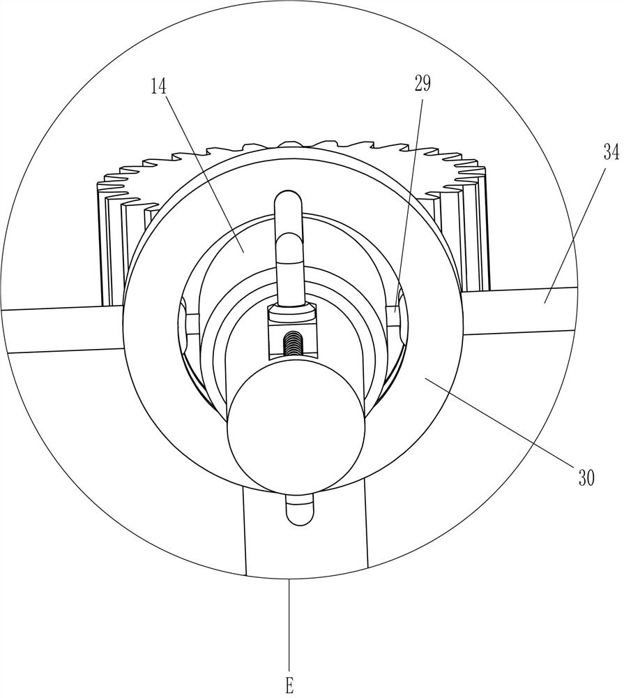
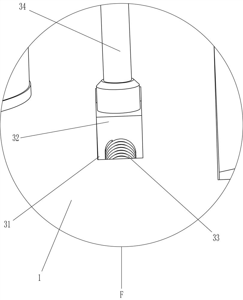
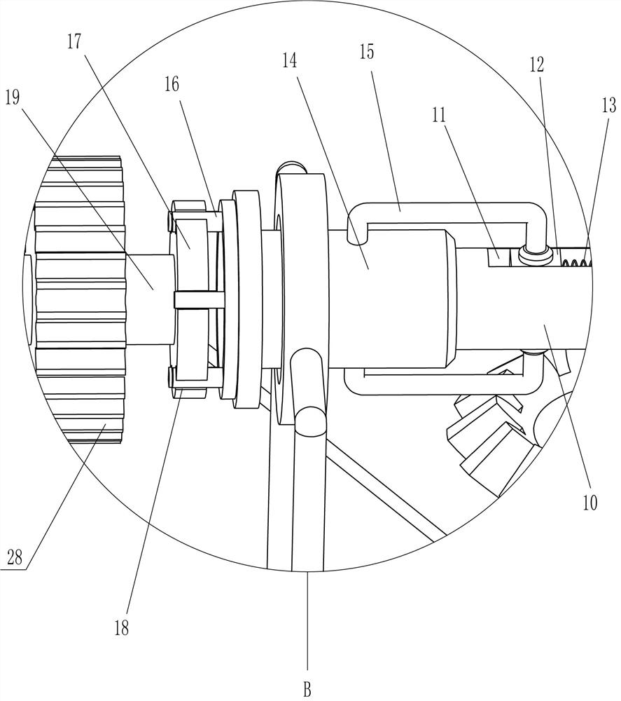
[0027] An orthopedic leg stretching device such as Figure 1-8 As shown, it includes a base 1, a support plate 2, a first slide rail 3, a driving assembly, a clamping assembly, a disengagement assembly, a turning assembly and a pulling assembly. The base 1 is used to install the entire device, and the support plate 2 is installed by bolts. On the left side of the top of the base 1, the first slide rail 3 is rotatably installed on the support plate 2, the driving assembly is installed on the base 1, powered by a motor, and the clamping assembly is installed on the first slide rail 3, which is rotated. The fixed and detached components are installed on the first slide rail 3 and move by sliding; the direction-changing and rotating components are installed on the base 1 and rotate and change direction by rotating; the pulling components are installed on the base 1 and move by sliding , the pulling component is slidingly connected with the disengaging component.

[0028] Such as ...

Embodiment 2

[0040] On the basis of Example 1, such as figure 1 , 3 Shown in and 10, also include the second slide rail 37, the 3rd sliding block 39, the 3rd spring 40, stop bar 41, L-shaped bar 42, pull bar 43 and right-angle bar 44, groove 36 is opened on support plate 2 On the right side, the second slide rail 37 is installed on the support plate 2 by screws, the third slide groove 38 is opened on the second slide rail 37, the third slide block 39 is slidably installed in the third slide groove 38, and the third spring 40 is installed between the third slide block 39 and the second slide rail 37, the stop bar 41 is welded on the third slide block 39, the L-shaped bar 42 is installed on the stop bar 41, the L-shaped bar 42 is connected with the second slide bar Rail 37 is slidably connected, and pull bar 43 is welded on the 3rd slide block 39, and right-angle bar 44 is two, and front and back symmetrical formula is welded on first slide rail 3 right parts, and right-angle bar 44 coopera...


PUM


Abstract

The invention relates to a leg stretching device, in particular to a leg stretching device for orthopedics. The technical problem to be solved by the present invention is to provide an orthopedic leg stretching device which stably fixes the leg and can change the direction of stretching. A leg stretching device for orthopedics, comprising a base for installing the whole device; a support plate mounted on the base; a first slide rail rotatably mounted on the support plate; a drive assembly mounted on the base, Power is provided by a motor; the clamping component is installed on the first slide rail and fixed by rotation. The invention can automatically stretch the legs through the guiding cylinder and the circular shaft, which is convenient and fast. Through the cooperation of the horizontal plate and the snap ring, the legs can be quickly fixed to prevent the displacement of the legs when they are stretched. The bevel gear cooperates with the second bevel gear to transmit power when changing directions and stretching the legs.

Description

technical field [0001] The invention relates to a leg stretching device, in particular to a leg stretching device for orthopedics. Background technique [0002] Stretching the legs can make the cooperation between the ligaments, muscles and joints more gentle and reduce the possibility of injury. Includes active stretching and passive stretching. The so-called active stretching refers to mainly relying on the strength of the contracted muscles. When the patient's leg is rehabilitated, the leg needs to be stretched. [0003] The patent authorization announcement number is that the patent of CN209092628U is a kind of orthopedic clinical use leg stretching device. Involved in the field of orthopedic clinical technology. The invention includes a base and a leg fixing mechanism. The base is a rectangular parallelepiped. One end surface of the base is horizontally provided with a sliding cavity, wherein the sliding cavity is a rectangular groove penetrating two opposite surface...

Claims


Application Information

Patent Timeline
Patent Type & Authority Patents(China)
IPC IPC(8): A61H1/02
CPCA61H1/0237A61H1/0218A61H2201/1207
Inventor 李进梅其他发明人请求不公开姓名
Owner 李进梅
Why Eureka
Try Eureka