
Dust removal device of tundish overturning area and dust removal method thereof

A technology of dust removal device and tundish, which is applied in the direction of removing smoke and dust, separation method, cleaning method and utensils, etc., to reduce pollution, improve work efficiency, and enhance sealing effect.

Pending Publication Date: 2020-07-28
ZHANGJIAGANG HONGCHANG STEEL PLATE CO LTD +1
View PDF0 Cites 2 Cited by
  • Summary
  • Abstract
  • Description
  • Claims
  • Application Information

AI Technical Summary

Problems solved by technology

[0003] Technical problem to be solved: Aiming at the above technical problems, the present invention provides a dust removal device and a dust removal method for the tundish turning area, which effectively solves the problem of dust in the slag dumping process and improves production efficiency

Method used


Image

  • Dust removal device of tundish overturning area and dust removal method thereof
  • Dust removal device of tundish overturning area and dust removal method thereof
  • Dust removal device of tundish overturning area and dust removal method thereof

Examples


Embodiment 1

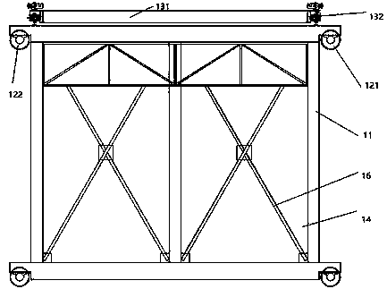
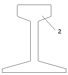
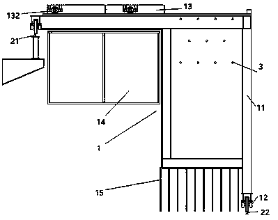
[0026] Such as figure 1 , figure 2 , Image 6 with Figure 7 As shown, a dust removal device for a tundish turning area includes a dust removal vehicle 1, a sliding track 2 and a spray system 3. The dust removal vehicle 1 is arranged on the sliding track 2 and located above the turning area. The sliding rail 2 includes an upper rail 21 and a ground rail 22. The upper rail 21 and the ground rail 22 are respectively arranged on both sides of the turning area. The upper rail 21 is laid on the beam extending from the factory column and above the turning area. The spray system 3 includes a spray pipe 31 and a nozzle 32. The spray pipe 31 is parallel to the sliding track 2 and passes through the top of the dust removal vehicle 1. The nozzles 32 are equally spaced in the spray pipe 31 on. There are 11 spray pipes 31 in total, 4 in the top layer, 3 in the middle layer, and 4 in the bottom layer. Each spray pipe 31 has a diameter of about 60 mm and is fixed on the dust removal vehicl...

Embodiment 2

[0031] Such as image 3 , Figure 4 , Figure 5 , Image 6 with Figure 7 As shown, a dust removal device for a tundish turning area includes a dust removal vehicle 1, a sliding track 2 and a spray system 3. The dust removal vehicle 1 is arranged on the sliding track 2 and located above the turning area. The sliding rail 2 includes an upper rail 21 and a ground rail 22. The upper rail 21 and the ground rail 22 are respectively arranged on both sides of the turning area. The upper rail 21 is laid on the beam extending from the factory column and above the turning area. The spray system 3 includes a spray pipe 31 and a nozzle 32. The spray pipe 31 is parallel to the sliding track 2 and passes through the top of the dust removal vehicle 1. The nozzles 32 are equally spaced in the spray pipe 31 on. There are 11 spray pipes 31 in total, 4 in the top layer, 3 in the middle layer and 4 in the bottom layer. The interlayer spacing is 800 mm, the interlayer spacing is 1000 mm, and the ...


PUM


Abstract

The invention discloses a dust removal device of a tundish overturning area and a dust removal method thereof. The dust removal device comprises a dust removal vehicle, a sliding rail and a spraying system; the dust removal vehicle is arranged on the sliding rail and located above an overturning area; the sliding rail comprises an upper rail and a ground rail which are arranged on the two sides ofthe overturning area correspondingly; the spraying system comprises a spraying pipe and nozzles, the spraying pipe is parallel to the sliding rail and penetrates through the top of the dust removal vehicle, the nozzles are arranged on the spraying pipe at equal intervals; the dust removal vehicle comprises a frame, a large wheel set, a movable top cover, baffles and a soft curtain, the frame is aframe with the horizontal top face, the large wheel set is arranged at the bottom of the frame and slidably connected with the sliding rail, the movable top cover comprises a cover body and top coverdrives, the cover body is arranged above the top of the frame, and the top cover drives are arranged at the four corners of the cover body and movably connected with the frame; and the baffles are arranged on the peripheral side walls of the frame, and the soft curtains are arranged in gaps between the baffles and the frame. The dust removal device effectively solves the problem of dust raising in the tundish deslagging process, and the production efficiency is improved.

Description

Technical field [0001] The invention belongs to the technical field of metal smelting, and particularly relates to a dust removal device and a dust removal method for a tundish turning area. Background technique [0002] The tundish is a common metal liquid container in steelmaking plants. It is used to ensure the stable delivery of molten steel before the continuous casting machine. In daily production, it needs to be used in turn due to the loss of refractory materials. The replaced tundish is rebuilt after slagging and cleaning. On-line use, the dust in the flipping and dumping area is large, so a spray hood is added to the workshop, which has to be lifted by the main crane in the workshop every time, which affects the production rhythm of the workshop and the efficiency of slag dumping is low. Summary of the invention [0003] Technical problem solved: In view of the above technical problem, the present invention provides a dust removal device and a dust removal method for t...

Claims


Application Information

Patent Timeline
Patent Type & Authority Applications(China)
IPC IPC(8): B08B15/04B01D47/06B01D47/16B22D45/00
CPCB01D47/06B01D47/16B01D2258/02B08B15/04B22D45/005
Inventor 陈涛
Owner ZHANGJIAGANG HONGCHANG STEEL PLATE CO LTD
Learn More