Unlock instant, AI-driven research and patent intelligence for your innovation.
A hardware drilling equipment
What is Al technical title?
Al technical title is built by PatSnap Al team. It summarizes the technical point description of the patent document.
A drilling equipment and hardware technology, applied in the field of hardware, can solve the problems of drilling head and object damage, hard slipping, etc., and achieve the effect of preventing displacement
Active Publication Date: 2021-05-14
永州市迈锐客科技有限公司
View PDF5 Cites 0 Cited by
Summary
Abstract
Description
Claims
Application Information
AI Technical Summary
This helps you quickly interpret patents by identifying the three key elements:
Problems solved by technology
Method used
Benefits of technology
Problems solved by technology
[0006] In order to solve the above-mentioned technology, when the small hardware parts are in the shape of a sphere, the drilling head of the equipment is pressed against the apex of the sphere-shaped part. When drilling, due to the small force-bearing area with the object, it is easier to cause rigid slippage, resulting in drilling The problem of damage to holes and objects
Method used
Image
Click on the blue label to locate the original text in one second.
Reading with bidirectional positioning of images and text.
Examples
Embodiment 1
[0031] as attached figure 1 to attach Figure 5 Shown:
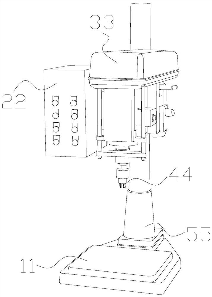
[0032] The present invention provides a hardware drilling device, the structure of which includes a workbench 11 , a console 22 , an implementing end 33 , a drilling head 44 , and a support rod 55 .
[0033] The upper surface of the workbench 11 is vertically welded with a support rod 55, and the end of the support rod 55 away from the workbench 11 is connected to the implementation end 33, and the lower end of the implementation end 33 is penetrated with a drilling head 44. The console 22 It is welded to the side surface of the implementation end 33.
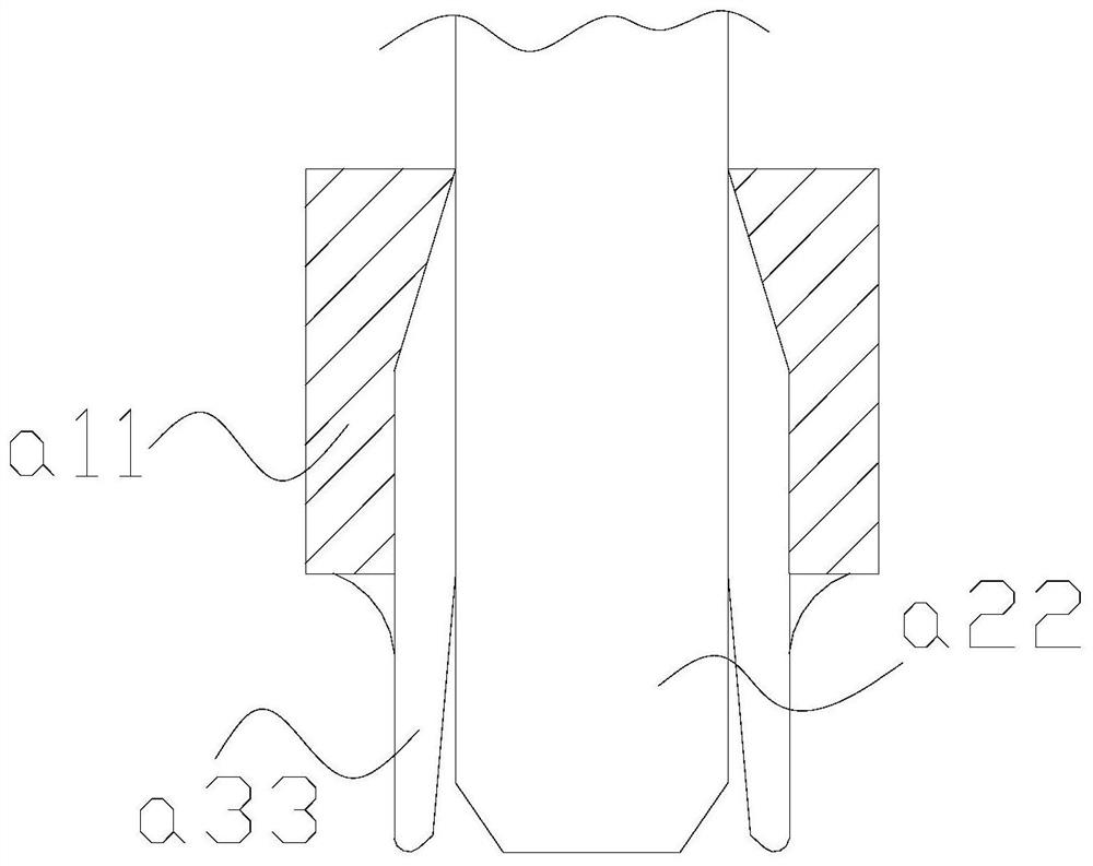
[0034] Wherein, the drilling head 44 includes an outer limiting shell a11, a drill body a22, and a supporting edge a33. The supporting edge a33 is against the outer surface of the drill body a22. The inner wall of the limit case a11, the support edge a33 evenly surrounds the outer surface of the drill body a22, the outer limit case a11 limits the overall expansion and ...
Embodiment 2
[0041] as attached Image 6 to attach Figure 8 Shown:
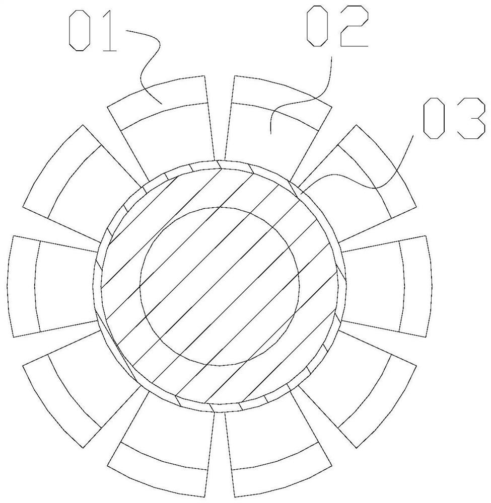
[0042] Wherein, the swing angle w22 includes a spacer e1, a force core e2, and an outer covering layer e3, the outer covering layer e3 is attached to the outer surface of the force core e2, and spacers are installed between the force cores e2 The strip e1, the force core e2 has a triangular structure and is evenly distributed in a fan shape, and the spacers e1 evenly space the active parts, and the force core e2 follows the arc required by the outer layer for bending and stretching.
[0043] Wherein, the force core e2 includes a return-shaped core m21 and an open angle m22. The return-shaped core m21 is against the outer surface of the open angle m22. The return-shaped core m21 is made of soft rubber material and has a certain degree of extrusion. Compression and resilience, the opening angle m22 bears the force on both sides and presses towards the middle, and the return-shaped core m21 gives the outer layer a certain...
PUM
Abstract
The invention discloses a hardware drilling equipment, the structure of which comprises a workbench, a control console, an implementation end, a drilling head, and a support rod. A support rod is welded vertically on the upper surface of the workbench. The end of the support rod far away from the workbench is connected to the implementation end. Connected to each other, let the implementation end drive the drilling head to move vertically downward, and the supporting edge will move down along the periphery of the hole, and the force-separating layer will play a role in protecting the force-bearing layer. When processing, fix the parts around the drilled hole to prevent displacement. The force core will bear the force of the outer layer and the outer layer, merge to a certain extent, and follow the arc required by the outer layer for bending and stretching , so that the main pocket body has a large area to bear the external force. When the force is bent between the two hard cores, it acts as a counter force, so that the force core can bend tightly, and can follow the arc when wrapping the edge of the sphere. Change, and play a counter force to push the package.
Description
technical field [0001] The invention belongs to the field of hardware, and more specifically relates to a hardware drilling device. Background technique [0002] There are many uses for small hardware parts. Some assembly methods require drilling. When drilling, fix the hardware and let the equipment apply force from top to bottom. Within a fixed range, carry out Drilling process, after leaving the hardware, the drilling is successful. [0003] Based on the inventor's discovery above, existing hardware drilling machines mainly have the following deficiencies, such as: [0004] When the small hardware parts are in the shape of a sphere, the drilling head of the equipment is against the apex of the sphere-shaped part. When drilling, due to the small force-bearing area with the object, it is easy to cause rigid slippage, resulting in the drilling head and the object. damage. [0005] Therefore need to propose a kind of hardware drilling equipment. Contents of the invention...
Claims
Application Information
Patent Timeline
Application Date:The date an application was filed.
Publication Date:The date a patent or application was officially published.
First Publication Date:The earliest publication date of a patent with the same application number.
Issue Date:Publication date of the patent grant document.
PCT Entry Date:The Entry date of PCT National Phase.
Estimated Expiry Date:The statutory expiry date of a patent right according to the Patent Law, and it is the longest term of protection that the patent right can achieve without the termination of the patent right due to other reasons(Term extension factor has been taken into account ).
Invalid Date:Actual expiry date is based on effective date or publication date of legal transaction data of invalid patent.

