Supercharge Your Innovation With Domain-Expert AI Agents!

Laser welding head and welding equipment

A laser welding head and laser technology, applied in laser welding equipment, welding equipment, welding/welding/cutting items, etc., can solve the problems of high labor cost, low welding quality, spatter, etc., and achieve the effect of reducing labor cost

Active Publication Date: 2020-07-28
佛山根固激光科技有限公司
View PDF7 Cites 0 Cited by
  • Summary
  • Abstract
  • Description
  • Claims
  • Application Information

AI Technical Summary

Problems solved by technology

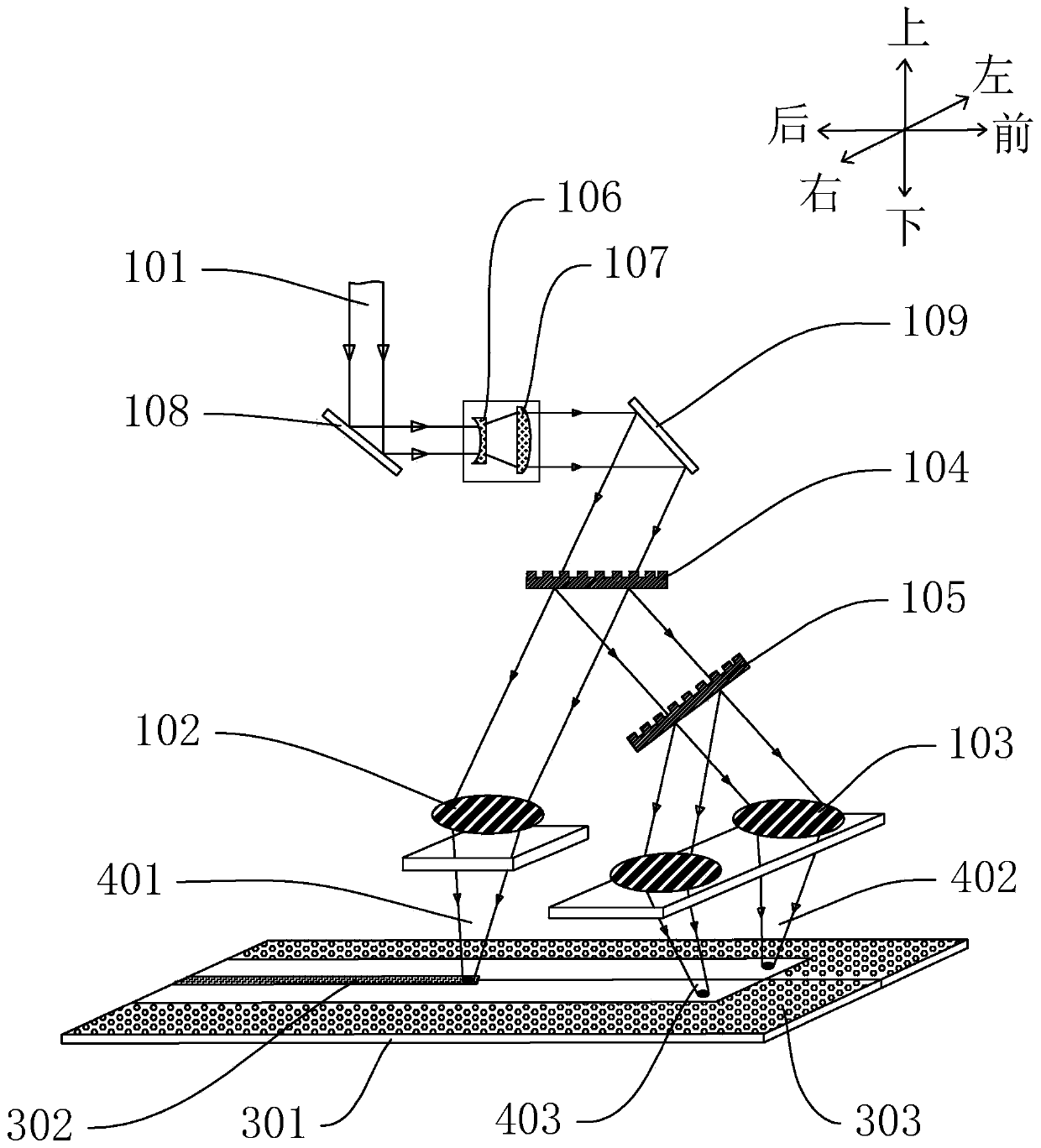
When welding stainless steel, the film on the surface of the stainless steel will greatly reduce the welding quality. During welding, the coating near the gap between the two plates will flow to the molten pool, which will interfere with the liquid phase flow of the molten pool and easily cause holes, pores or splashes , and even serious defects such as undercut
Therefore, it is necessary to remove the film on the surface of the stainless steel before welding, but the current method of manually tearing the film by hand has high labor costs

Method used


Image

  • Laser welding head and welding equipment
  • Laser welding head and welding equipment

Examples


Embodiment Construction

[0023] Embodiments of the present invention are described in detail below, examples of which are shown in the drawings, wherein the same or similar reference numerals designate the same or similar elements or elements having the same or similar functions throughout. The embodiments described below by referring to the figures are exemplary only for explaining the present invention and should not be construed as limiting the present invention.

[0024] In the description of the present invention, it should be understood that the orientation descriptions, such as up, down, front, back, left, right, etc. indicated orientations or positional relationships are based on the orientations or positional relationships shown in the drawings, and are only In order to facilitate the description of the present invention and simplify the description, it does not indicate or imply that the device or element referred to must have a specific orientation, be constructed and operated in a specific ...


PUM

PropertyMeasurementUnit
Angleaaaaaaaaaa

Abstract

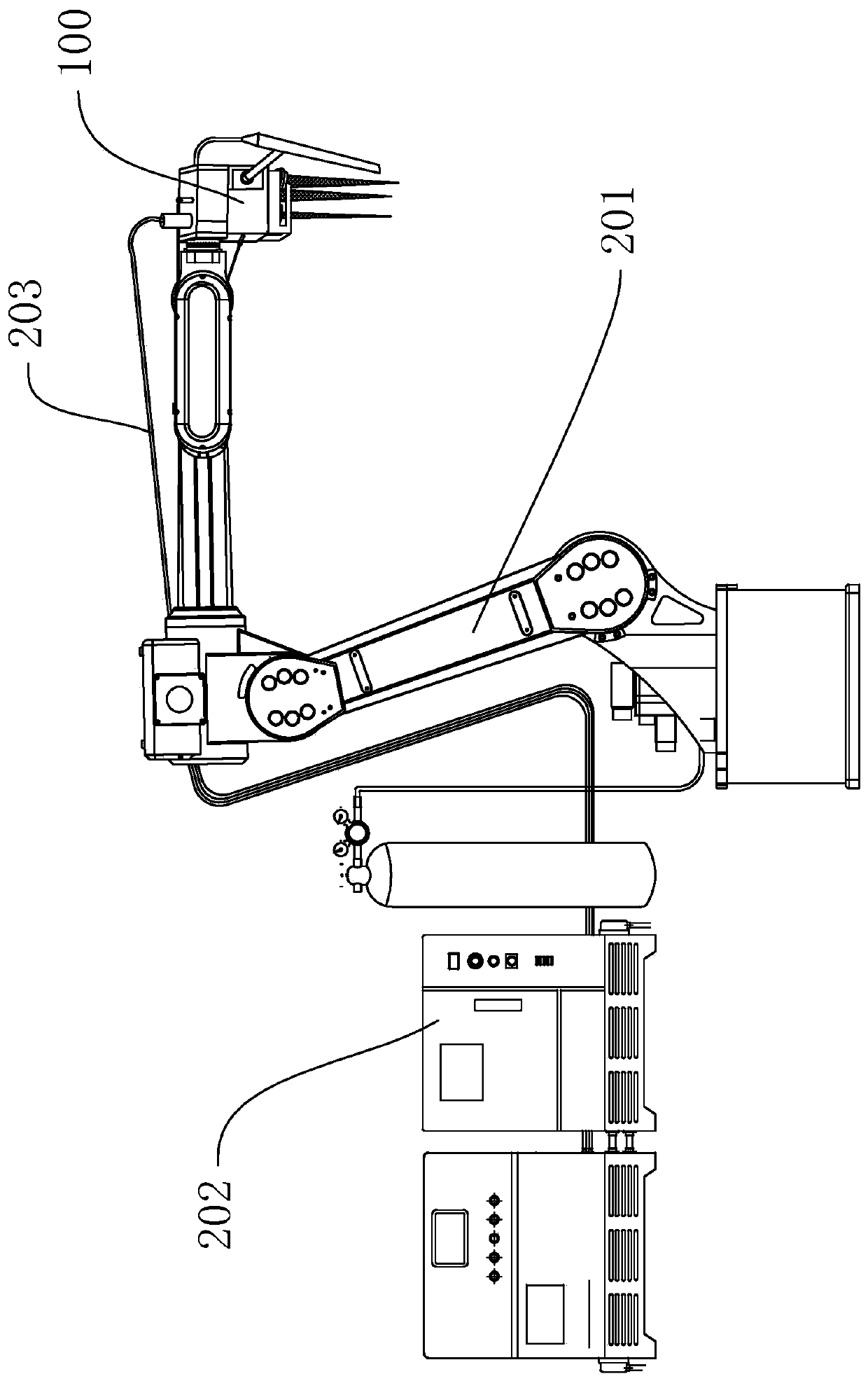
The invention discloses a laser welding head and welding equipment provided with the laser welding head. The laser welding head comprises a laser source, a rear powerful laser output head, a front weak laser output assembly which is relatively fixed to the front side of the rear powerful laser output head, and a light guide device, wherein the front weak laser output assembly can output laser withstrength lower than that of the rear powerful laser output head; and the light guide device is used for guiding output light of the laser source to the front weak laser output assembly and the rear powerful laser output head. In a welding process, laser output by the front weak laser output assembly firstly heat films at the two sides of a welding seam, and the films are removed after being heated; and then, laser output by the rear powerful laser output head heats and welds the welding seam. According to the laser welding head disclosed by the invention, film removing and welding are integrated, so that automatic film removal is simultaneously performed at the front side of a welding spot, and therefore, an existing manual film tearing way is avoided, and labor cost is reduced.

Description

technical field [0001] The invention relates to the field of welding technology, in particular to a laser welding head and welding equipment. Background technique [0002] Laminated stainless steel refers to stainless steel with a thin film on the surface, which plays a role in protecting the surface of stainless steel during transportation. Laminated stainless steel is the main production material in the home appliance and kitchen utensils industries. When welding stainless steel, the film on the surface of the stainless steel will greatly reduce the welding quality. During welding, the coating near the gap between the two plates will flow to the molten pool, which will interfere with the liquid phase flow of the molten pool and easily cause holes, pores or splashes , and even serious defects such as undercut. Therefore, the film on the surface of the stainless steel needs to be removed before welding, but the current method of manually tearing the film by hand has high la...

Claims


Application Information

Patent Timeline
IPC IPC(8): B23K26/21B23K26/324B23K26/60B23K26/70B23K26/354B23K103/16
CPCB23K26/324B23K26/21B23K26/354B23K26/60B23K26/702B23K2103/166
Inventor 唐霞辉张旭辉彭浩刘宇阳殷凡超邹锋
Owner 佛山根固激光科技有限公司
Features
  • R&D
  • Intellectual Property
  • Life Sciences
  • Materials
  • Tech Scout
  • Unparalleled Data Quality
  • Higher Quality Content
  • 60% Fewer Hallucinations
Learn More