A beam end prestressed structure and its construction method

A prestressed structure and construction method technology, applied in bridges, bridge construction, bridge materials, etc., can solve problems such as difficulty in ensuring the quality of prestressed construction, difficulty in meeting production requirements, cutting off of main reinforcement under transverse force, etc., to reduce adverse effects, The effect of shortening the construction period and enhancing the overall mechanical performance

Active Publication Date: 2021-11-26
POWERCHINA ZHONGNAN ENG
View PDF6 Cites 0 Cited by
  • Summary
  • Abstract
  • Description
  • Claims
  • Application Information

AI Technical Summary

Problems solved by technology

The disadvantages of these methods are: the loss of prestress in method 1 single-end tension is large, and when the height of the box girder is small, the tension in the box room is also relatively difficult, and the construction quality of prestress is difficult to guarantee; method 2 prefabricated T-beam The erection must be carried out after the prestressed steel tendons of the box girder are stretched. The construction efficiency is low, the construction period is long, and it is difficult to meet the production requirements; method 3. The notches on the top plate of the box girder will cause a large amount of lateral force on the top plate of the end beam of the box girder The main rib was cut off, leaving a safety hazard

Method used


Image

  • A beam end prestressed structure and its construction method
  • A beam end prestressed structure and its construction method
  • A beam end prestressed structure and its construction method

Examples


Embodiment Construction

[0037] The present invention will be described in detail below with reference to the accompanying drawings and examples. It should be noted that, in the case of no conflict, the embodiments of the present invention and the features in the embodiments can be combined with each other. For the convenience of description, if the words "up", "down", "left" and "right" appear in the following, it only means that the directions of up, down, left and right are consistent with the drawings themselves, and do not limit the structure.

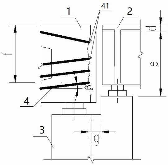
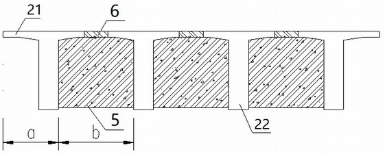
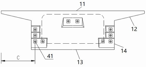
[0038] A beam end prestressed structure such as figure 1 As shown, it includes box girder 1, T girder structure, pier 3, prestressed steel beam 4, the adjacent span of the box girder 1 is the T girder structure, and the box girder 1 and the The junction of the T-beam structure is located on the pier 3. The T-beam structure includes an end beam 5 and a T-beam 2. The T-beam 2 has multiple pieces, and each piece of the T-beam 2 includes a T-beam flange plat...


PUM


Abstract

A beam end prestressed structure, comprising a box girder, a T-beam structure, a bridge pier, and prestressed steel strands, the adjacent span of the box girder is the T-beam structure, and the box girder and the described box girder of each adjacent span The junction of the T-beam structure is located on the bridge pier, and a plurality of T-beams are connected in the width direction of the bridge through the end beam at the beam end, and a plurality of the prestressed steel beams are arranged in the box girder, and the prestressed steel tendons are arranged in the box girder. The anchorage points at both ends of the stress steel tendon are located in the end beam region of the T-beam of the adjacent span in the width direction of the bridge, and the prestressed steel tendon is parallel to the vertical plane where the bridge axis is located. The prestressed steel tendons of the box girder are tensioned at both ends, which can not only reduce the loss of prestressed stress, but also make the stress on the prestressed steel tendons uniform and ensure safety. The prestressed tension space is set within the area of ​​the end beam of the T-beam structure, so that there is sufficient space for the prestressed tension of the box girder without affecting the erection of the T-beam ribs, thereby effectively shortening the construction period and improving work efficiency.

Description

technical field [0001] The invention relates to the field of road and bridge design and construction, in particular to a beam end prestressed structure and a construction method thereof. Background technique [0002] Box girder is a kind of middle beam in bridge engineering. It is hollow inside and has flange plates on both sides of the upper part. It is named for its similarity to a box. T-beam refers to a beam with a T-shaped cross-section. It is composed of horizontal flange plates and vertical beam ribs. Several T-beams are connected by end beams at the beam ends. For bridges composed of cast-in-situ box girders and prefabricated T girders, the current domestic prestressed beam distribution design scheme is that the longitudinal prestressed steel tendons in the box girder need to be anchored and stretched at the joint ends, and are affected by the prefabricated T girder ribs and end beams. The current commonly used tensioning methods are: 1. The longitudinal prestressed...

Claims


Application Information

Patent Timeline
Patent Type & Authority Patents(China)
IPC IPC(8): E01D2/04E01D21/00E01D101/28
CPCE01D2/04E01D21/00E01D2101/28
Inventor 谭满江刘朝晖侯嘉庆秦波王宏贵
Owner POWERCHINA ZHONGNAN ENG
Why Eureka
Try Eureka