
Large-range wall painting device for building

A large-scale, architectural technology, applied in the direction of construction, building structure, etc., can solve the problems of limited stroke of the lifting device and small painting range, and achieve the effect of large range and high efficiency

Active Publication Date: 2020-07-28
杜春雷 +3
View PDF8 Cites 1 Cited by
  • Summary
  • Abstract
  • Description
  • Claims
  • Application Information

AI Technical Summary

Problems solved by technology

[0004] The existing painting device generally uses the lifting device to drive the painting roller up and down for painting, but the stroke of the lifting device is limited, resulting in a relatively small painting area

Method used


Image

  • Large-range wall painting device for building
  • Large-range wall painting device for building
  • Large-range wall painting device for building

Examples


Embodiment 1

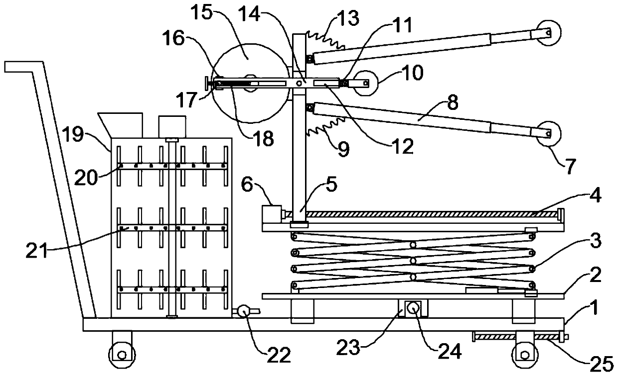
[0023] see Figure 1~2 , in an embodiment of the present invention, a large-scale wall painting device for construction includes a trolley 1, a paint supply unit installed on the trolley 1, and a painting unit, and the paint supply unit includes a preparation cylinder 19 and a stirring assembly 21 and a supply pipe, the top of the preparation cylinder 19 is provided with a feed inlet, the bottom is connected with a supply pipe, and a booster pump 22 is installed on the supply pipe, and the stirring assembly 21 includes a stirring shaft, a stirring rod and is used to drive the stirring shaft to rotate The stirring motor, the stirring shaft is installed in the preparation cylinder 19 for rotation, the stirring shaft is located on the shaft section in the preparation cylinder 19 and rotates from top to bottom to install a plurality of stirring rods, and the stirring rods are fixedly installed with The stirring rod has a wave-shaped hole 20 on the stirring rod, and the stirring sh...

Embodiment 2

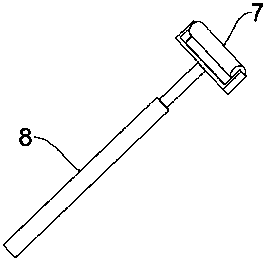
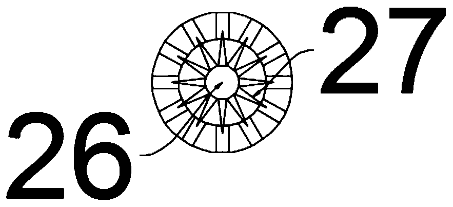
[0026] see image 3 The difference between the embodiment of the present invention and embodiment 1 is that the first painting roller 7 and the second painting roller 10 are provided with an air bag 26, and the air bag 26 is integrally provided with a nozzle extending into the spray hole. The adjustment protrusion 27, the air bag 26 is connected with a connecting pipe, and a valve is installed on the connecting pipe, and the volume of the adjustment protrusion 27 can be adjusted by inflating or deflating the air bag 26, thereby adjusting the size of the nozzle hole to meet different painting requirements. Adaptable.

[0027]The working principle of the present invention is: when working, the height is adjusted by the lifting mechanism, and then the second forward and reverse motor 6 drives the third mounting plate 5 close to the wall, and the two first painting rollers 7 are respectively along the upper and lower sides of the wall. until it moves to the top and bottom of the ...


PUM


Abstract

The invention discloses a large-range wall painting device for a building, and relates to the technical field of building equipment. The large-range wall painting device mainly aims at solving the problem that an existing painting device is small in painting range. The painting device comprises a cart, a coating supply unit and a painting unit, wherein the coating supply unit and the painting unitare arranged on the cart; and the painting unit comprises a first mounting plate, a second mounting plate, a third mounting plate and a painting assembly, the painting assembly comprises electric push rods, first painting rollers, a second painting roller and a driving mechanism used for driving the second painting roller to move, and the driving mechanism comprises a driving motor, a rotating disc, an adjusting block, an adjusting screw, a cylindrical pin, a swing rod and a connecting rod. The painting unit is arranged, the third mounting plate is driven to be close to the wall surface, thetwo first painting rollers move towards the upper side and lower side along the wall surface until the two first painting rollers move to the top and the bottom of the wall surface, and the driving mechanism drives the second painting roller to swing to paint the area in the middle position so that painting of the whole wall surface height can be achieved at a time, the range is large, and efficiency is high.

Description

technical field [0001] The invention relates to the technical field of construction equipment, in particular to a large-scale wall plastering device for construction. Background technique [0002] Construction refers to the assets made by man-made construction, which belongs to the category of fixed assets, including two categories: houses and structures. Housing refers to engineering buildings for people to live, work, study, produce, operate, entertain, store items and carry out other social activities. The difference from buildings is structures, which refer to engineering buildings other than houses, such as walls, roads, dams, wells, tunnels, water towers, bridges and chimneys, etc.; [0003] Whitewashing refers to putting a layer of mortar on the wall surface of the house to protect the wall and increase the beauty of the house; [0004] Existing painting devices generally use a lifting device to drive the painting roller up and down for painting, but the stroke of t...

Claims


Application Information

Patent Timeline
IPC IPC(8): E04F21/08E04F21/12
CPCE04F21/08E04F21/12
Inventor 陈本英
Owner 杜春雷
Features
  • Generate Ideas
  • Intellectual Property
  • Life Sciences
  • Materials
  • Tech Scout
  • Unparalleled Data Quality
  • Higher Quality Content
  • 60% Fewer Hallucinations
Learn More