
Gradual-mode water turbine

A water turbine, progressive technology, applied in the field of impact water turbine, can solve the problems of small adaptability, pollution phenomenon, large hydraulic loss, etc.

Inactive Publication Date: 2020-07-28
黄国宏
View PDF2 Cites 1 Cited by
  • Summary
  • Abstract
  • Description
  • Claims
  • Application Information

AI Technical Summary

Problems solved by technology

[0005] The purpose of the present invention is to overcome the shortcomings of low water energy conversion efficiency, large hydraulic loss, small adaptable surface, and pollution phenomenon in the currently used water turbines and existing water turbine technical solutions, and provide a water flow pressure energy Fully converted into rotational mechanical energy, stable and reliable operation performance, clean and pollution-free in the manufacturing and operation process, and can adapt to medium and low water heads and various flow rates of water energy resource environments.

Method used


Image

  • Gradual-mode water turbine
  • Gradual-mode water turbine
  • Gradual-mode water turbine

Examples


Embodiment Construction

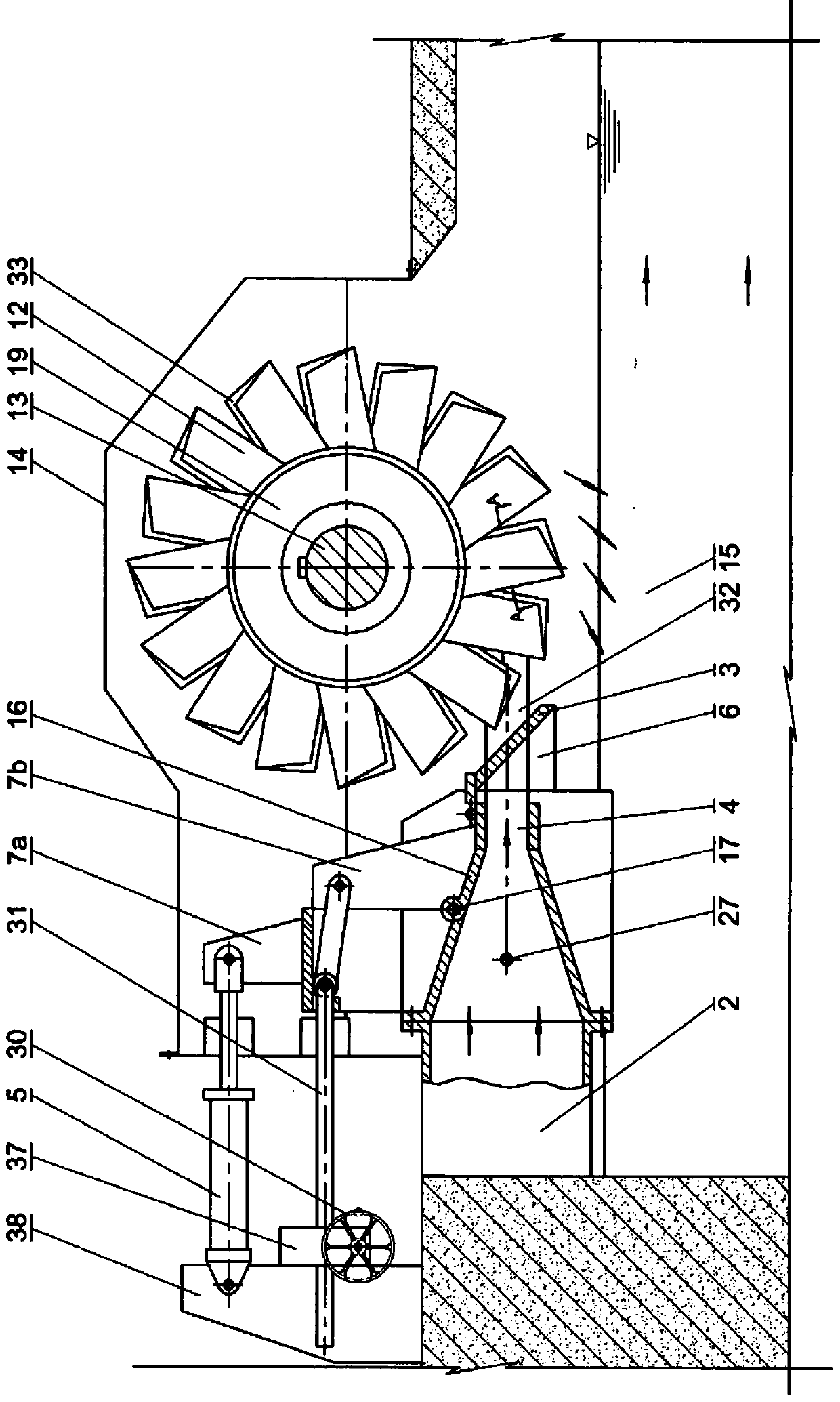
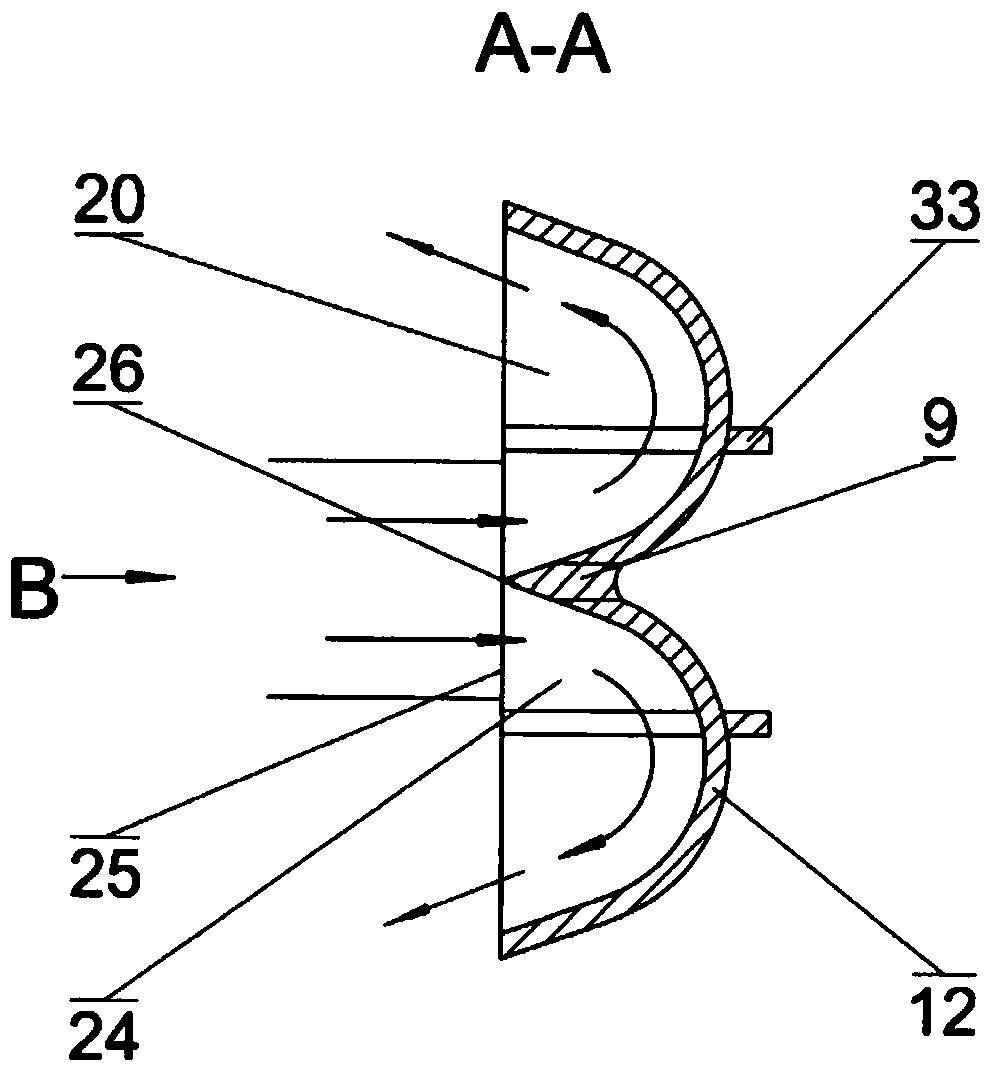
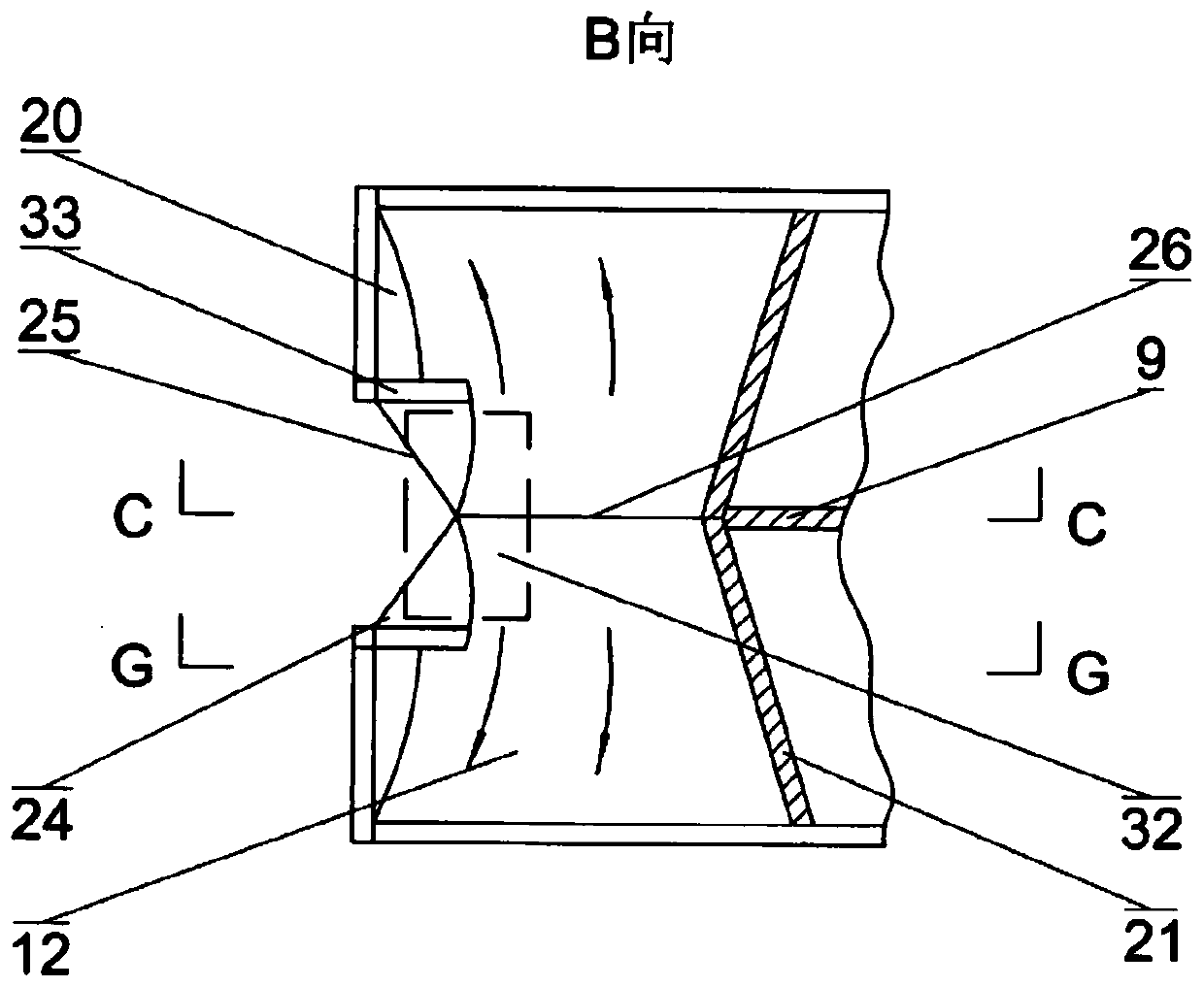
[0044] figure 1 , figure 2 , image 3 , Figure 4 and Figure 5 A first embodiment of the invention is shown.

[0045] In this embodiment, the pressure water diversion chamber is connected with three rectangular pressure water diversion channels 2 arranged axially and horizontally, and respectively corresponding to the three runners installed on the main shaft 13 . One end of the main shaft 13 is indirectly rotationally connected to the main shaft of the generator through a speed increaser, and the other end is rotationally connected with a mechanical speed protection signal device.

[0046] As shown in the figure: the water outlet of the pressure water diversion channel 2 is equipped with a rectangular outlet 4, and the top of the outlet 4 is hinged with a rotary valve 16 that rotates according to the side shaft 17, and the top of the rotary valve 16 is provided with a transmission arm 7b. The arm 7 b is in transmission connection with the worm 31 , and the worm 31 is i...


PUM


Abstract

The invention discloses an impact-type gradual-mode water turbine which can adapt to various flow and water power resource environment under medium and low water heads in the technical field of hydraulic electro-generating. An ejecting device of the gradual-mode water turbine comprises one or several pressure water guiding channels and an ejecting opening of each pressure water guiding channel, arotating moving door mounted in each channel or a rotating moving door hinged to each ejecting opening, a deflecting plate arranged at the front of each ejecting opening and an opening and controllingmechanism connected with each rotating moving door and each deflecting plate in a driving mode, a rotating device comprises one or more groove-shaped blades and inner-end guiding plate of each groove-shaped blade on both sides of a plurality of groups of groove water dividing blades arranged on a wheel hub and the outer circumference of the wheel hub and arranged on a spindle, two water inlet water dividing blades formed after bifurcating of the outer end of each groove water dividing blade and a water inlet water dividing plate of each water inlet water dividing blade and rotating wheels formed by isolating supporting plates arranged among each water inlet water dividing plate, each outer end water outlet part water guiding plate and the back of the groove-shaped blade, and each ejectingopening corresponds to the corresponding groove water dividing blade and every two water inlet water dividing blades. The water turbine adapts to various water power resources under medium and low water heads, the manufacturing and operation process is clean and has no pollution, and the water energy conversion efficiency can achieve full efficiency.

Description

technical field [0001] The invention belongs to the impact type water turbine in the technical field of hydroelectric power generation, and in particular relates to a water energy resource environment suitable for medium and low water heads and various flow rates, and the manufacturing and operation process is clean and pollution-free, and the water energy conversion efficiency can realize full efficiency. Impact type progressive water turbine. Background technique [0002] At present, the high-efficiency impact-type bucket water turbine used in hydropower production is mainly composed of a runner on the main shaft, which is composed of a wheel hub and concave-shaped water buckets on both sides of a number of water blades arranged around it. and other components; the ejection device is mainly composed of a circular nozzle, a circular spray needle installed in it, and a deflector installed in the front of the nozzle. The disadvantages are: in order to prevent the jet from sh...

Claims


Application Information

Patent Timeline
Patent Type & Authority Applications(China)
IPC IPC(8): F03B3/18F03B3/00F03B11/00F03B13/00
CPCF03B3/00F03B3/183F03B11/00F03B13/00Y02E10/20Y02P70/50
Inventor 黄国宏
Owner 黄国宏
Learn More