External gas-liquid cabin and wave energy power generation device
What is AI technical title?
AI technical title is built by PatSnap AI team. It summarizes the technical point description of the patent document.
A power generation device, external technology
Pending Publication Date: 2020-07-28
HANGZHOU HUGEWAVE ENERGY TECH CO LTD
View PDF2 Cites 1 Cited by
Summary
Abstract
Description
Claims
Application Information
AI Technical Summary
This helps you quickly interpret patents by identifying the three key elements:
Problems solved by technology
Method used
Benefits of technology
Problems solved by technology
The defect of this type of power generation device is that the structure is complicated, the response and utilization rate of the long center pipe to waves are low, and it cannot be modified on the basis of existing buoys or buoys so that the existing buoys or buoys have power generation function
Method used
Image
Click on the blue label to locate the original text in one second.
Reading with bidirectional positioning of images and text.
Examples
Embodiment 1
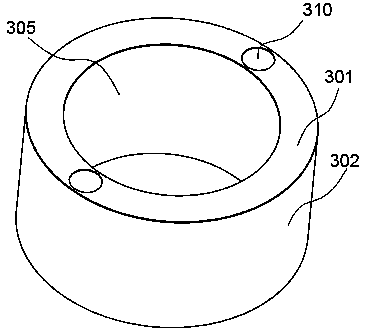
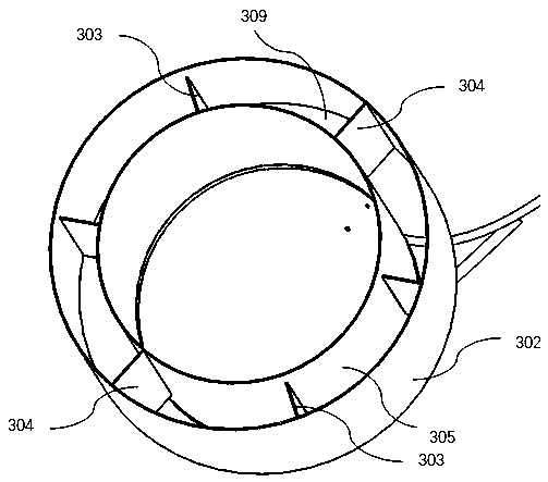
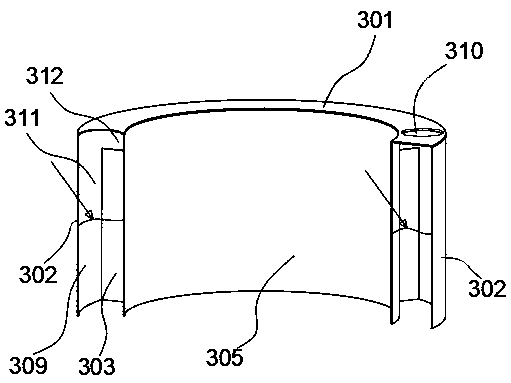
[0062] An external gas-liquid tank of this embodiment has a structure such as Figure 1A , Figure 1B , Figure 1C As shown, it is used to configure and install on the outside of a floating body (also called a marine buoy).
[0063] like Figure 1A , Figure 1B and Figure 1C As shown, the external gas-liquid tank 3 of the present embodiment has an annular inner wall 305 of the gas-liquid tank, an outer wall 302 of the gas-liquid tank opposite to the inner wall 305 of the gas-liquid tank, and an inner wall 305 of the gas-liquid tank and an outer wall 302 of the gas-liquid tank The gas-liquid tank upper wall 301 that the upper ends of all are sealed and connected.
[0064] Wherein, the upper wall 301 of the gas-liquid tank is uniformly provided with two air vents 310 in the circumferential direction. It should be noted that configuring two vents 310 is only a preferred implementation of this embodiment, and in practice only one or more than three vents may be configured acc...
Embodiment 2
[0074] An external gas-liquid tank of this embodiment has a structure such as Figure 2A , Figure 2B As shown, it is used to configure and install on the outside of a floating body (also called a marine buoy). The difference between this embodiment and the first embodiment is that it does not completely surround the outside of the floating body, but is arranged on a part of the outer wall of the floating body, that is, the external gas-liquid tank is not annular.
[0075] The external gas-liquid tank 3 of the present embodiment, such as Figure 2A , Figure 2B As shown, it includes an inner wall 305 of the gas-liquid chamber for adapting to part of the outer wall of the floating body, an outer wall 302 of the gas-liquid chamber opposite to the inner wall 305 of the gas-liquid chamber, and an inner wall 305 for connecting the inner wall 305 of the gas-liquid chamber to the gas-liquid chamber. The gas-liquid tank side wall 306 at the end of the tank outer wall 302 and the ga...
Embodiment 3
[0085] A kind of external gas-liquid tank 3 of the present embodiment, its structure is as follows Figure 5A , Figure 5B As shown, it is used to configure and install on the outside of the buoy 2 (also known as ocean buoy).
[0086] like Figure 5A, Figure 5B As shown, the external gas-liquid tank 3 of this embodiment includes a gas-liquid tank outer wall 302 of a cylindrical structure and an gas-liquid tank upper wall 301 covering the upper end of the gas-liquid tank outer wall 302, wherein the gas-liquid tank upper wall 301 A vent 310 is provided, and the vent 310 is used for installing the air turbine and generator system 1 .
[0087] like Figure 5B As shown, in this embodiment, the gas-liquid chamber 309 is formed inside the outer wall 302 of the gas-liquid chamber of the cylindrical structure and the upper wall 301 of the gas-liquid chamber. The gas-liquid cavity 309 can fluctuate in the gas-liquid cavity 309, and the air vent 310 communicates with the gas-liquid...
PUM
Abstract
The invention relates to the technical field of ocean renewable energy utilization, and particularly discloses an external gas-liquid cabin and a wave energy power generation device. The external gas-liquid cabin is used for being arranged on the outer side of a floating body, and the wave energy power generation device comprises the floating body, the external gas-liquid cabin arranged on the outer side of the floating body, and an air turbine and a power generator system arranged on the external gas-liquid cabin. The external gas-liquid cabin is arranged on the outer side of the floating body, the space of the top of the floating body is not occupied, meanwhile, an existing ocean buoy or floating body can be conveniently transformed, and the existing ocean buoy or floating body is additionally provided with a wave energy power generation function to supplement electric energy supply; and due to the fact that transformation of the existing ocean buoy or floating body can be achieved through low cost and a simple process, industrial popularization of the technology is facilitated.
Description
technical field [0001] The invention relates to the technical field of marine renewable energy utilization, in particular to an external gas-liquid tank and a wave energy generating device. Background technique [0002] Ocean buoys are important carriers for carrying ocean observation and communication equipment. Because it is necessary to have sufficient power supply for ocean observation and communication, the current way to power ocean buoys is to use solar energy and wind energy to power batteries, but because the energy density of solar energy and wind energy is low and unstable, so For functional buoys with large power consumption, solar energy and wind energy often cannot meet their needs. [0003] Wave energy is a widely distributed, high energy density (more than 300 times that of solar energy and more than 80 times that of wind energy), and very stable renewable energy (an average annual utilization time of more than 5,000 hours). Therefore, it is very valuable a...
Claims
Application Information
Patent Timeline
Application Date:The date an application was filed.
Publication Date:The date a patent or application was officially published.
First Publication Date:The earliest publication date of a patent with the same application number.
Issue Date:Publication date of the patent grant document.
PCT Entry Date:The Entry date of PCT National Phase.
Estimated Expiry Date:The statutory expiry date of a patent right according to the Patent Law, and it is the longest term of protection that the patent right can achieve without the termination of the patent right due to other reasons(Term extension factor has been taken into account ).
Invalid Date:Actual expiry date is based on effective date or publication date of legal transaction data of invalid patent.

