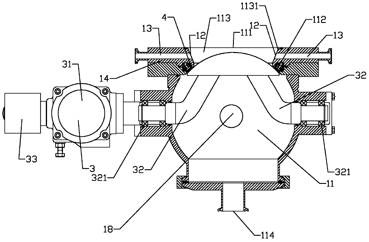
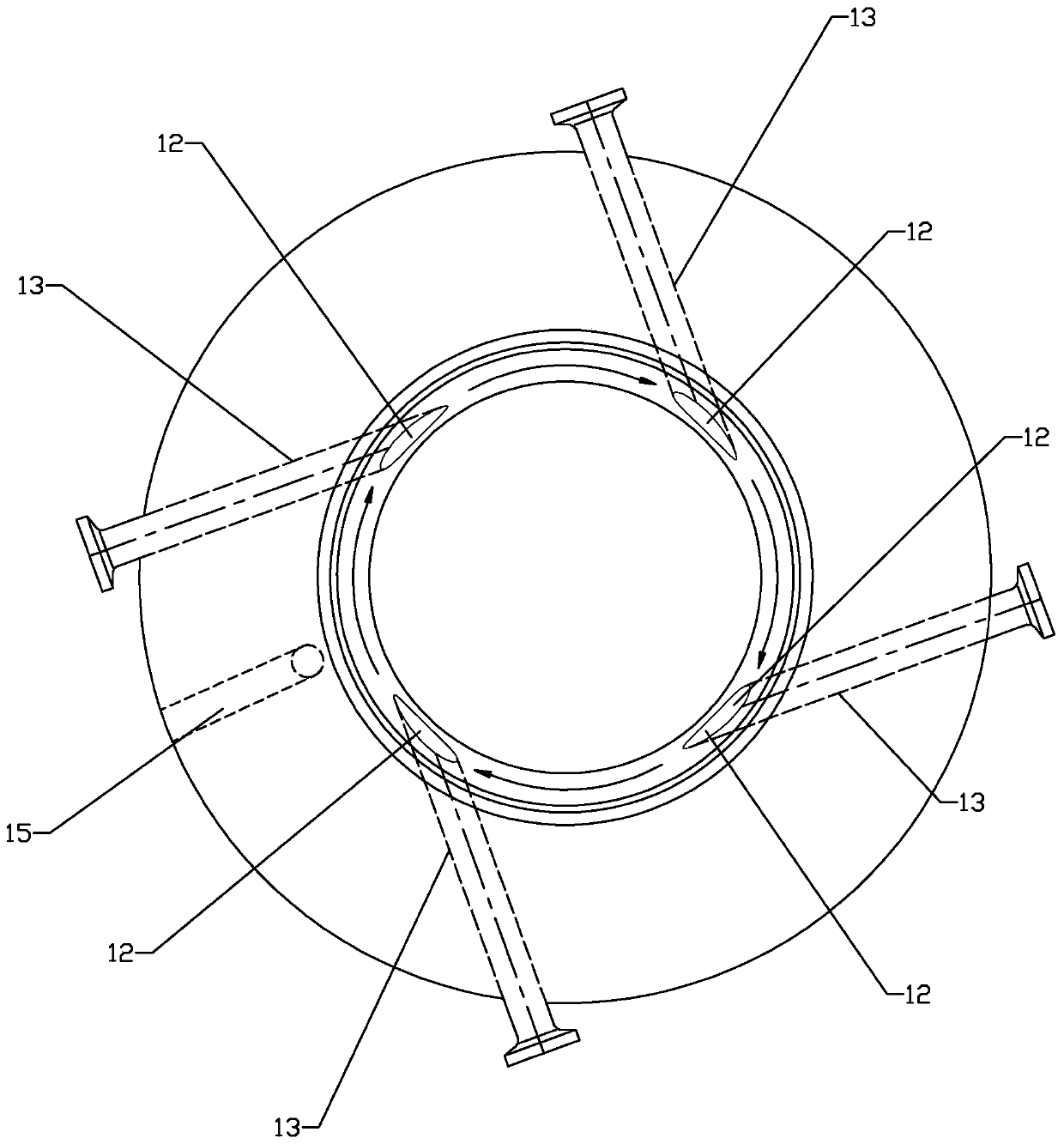
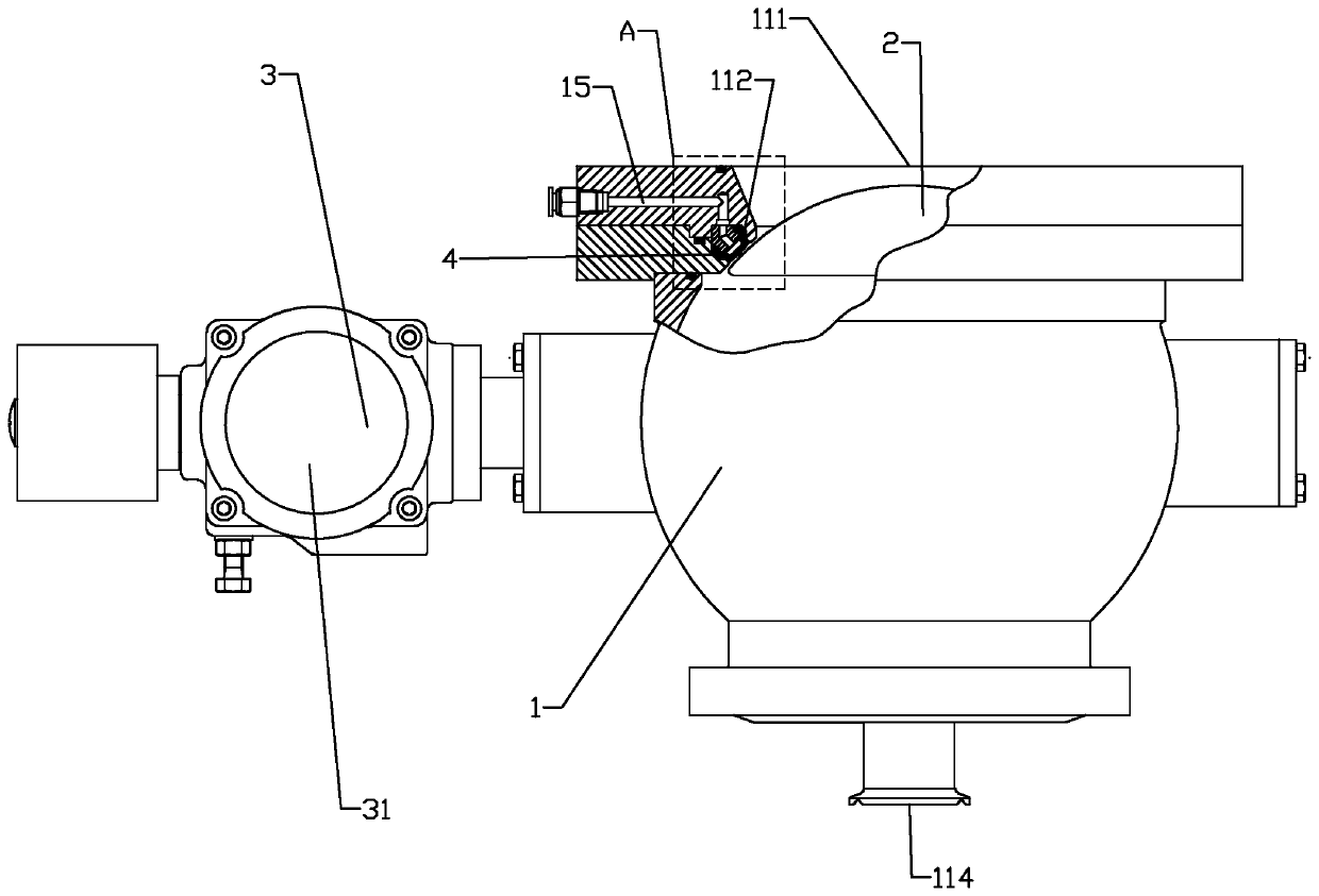
Valve with purging structure

A technology for valves and purge ports, applied to valve devices, cleaning methods and appliances, cocks including cut-off devices, etc., which can solve problems affecting production efficiency and short service life of sealing rings

Pending Publication Date: 2020-07-28
浙江亚光科技股份有限公司
View PDF0 Cites 1 Cited by
  • Summary
  • Abstract
  • Description
  • Claims
  • Application Information

AI Technical Summary

Problems solved by technology

Unable to meet the requirements of aseptic pharmaceuticals and shorten the service life of the sealing ring, which affects production efficiency

Method used


Image

  • Valve with purging structure
  • Valve with purging structure
  • Valve with purging structure

Examples


Embodiment Construction

[0036] The technical solutions of the present invention will be clearly and completely described below in conjunction with the accompanying drawings. Apparently, the described embodiments are some of the embodiments of the present invention, but not all of them. Based on the embodiments of the present invention, all other embodiments obtained by persons of ordinary skill in the art without making creative efforts belong to the protection scope of the present invention.

[0037] In the description of the present invention, it should be noted that the terms "center", "upper", "lower", "left", "right", "vertical", "horizontal", "inner", "outer" etc. The indicated orientation or positional relationship is based on the orientation or positional relationship shown in the drawings, and is only for the convenience of describing the present invention and simplifying the description, rather than indicating or implying that the referred device or element must have a specific orientation, ...


PUM


Abstract

The invention relates to a valve with a purging structure. The valve comprises a valve body, a valve element and a valve element driving device, a flow channel is formed in the valve body and is provided with a communicating end communicating with an equipment tank body and a cut-off opening in sealing fit with the valve element, and the valve element driving device drives the valve element to beclose to or away from the cut-off opening to form cut-off and communication of the flow channel; an area, located between the communicating end and the cut-off opening, of the flow channel serves as acommunicating area, a plurality of purging openings are formed in the area, located in the communicating area, of the flow channel, purging channels extending to the outer side of the valve body fromthe flow channel are formed in the positions, corresponding to the purging openings, of the valve body, and the positions, located on the outer side of the valve body, of the purging channels communicate with an air source. By the adoption of the scheme, the valve with the purging structure can prevent a material static area from being generated between a stirrer and the valve, and therefore themoisture content or uniformity of materials is guaranteed.

Description

technical field [0001] The invention relates to the field of material drying or equipment tanks, in particular to a valve with a purging structure. Background technique [0002] In the pharmaceutical industry, some materials need to be dried or mixed to make the moisture content or uniformity of the materials meet the process requirements, and the operation process is fully enclosed to avoid contamination by foreign matter or microorganisms. [0003] Drying or equipment tanks are often equipped with valves for discharging materials, and in order to avoid metal foreign objects caused by scraping between the agitator and the valve during agitation, a certain amount of safety is often reserved between the agitator and the valve. gap. However, because of the setting of the safety gap, there will be a material static area between the agitator and the valve where the material cannot flow. Since the material in the static area cannot participate in the complex diffusion process, t...

Claims


Application Information

Patent Timeline
IPC IPC(8): F16K5/06F16K5/08B08B5/02
CPCB08B5/02F16K5/0605F16K5/0647F16K5/0663
Inventor 何明洪刘亚洲林宝康王鸿坤尹智超林培高
Owner 浙江亚光科技股份有限公司
Why Eureka
Try Eureka