Engine temperature distribution calculation method and device and storage medium

A technology of engine temperature and temperature distribution, applied in the direction of calculation, computer-aided design, design optimization/simulation, etc., can solve the problems of reduced mechanical properties of engine parts, large number of parts, and inability to accurately calculate temperature distribution.

Pending Publication Date: 2020-07-28
SANY HEAVY MACHINERY
View PDF3 Cites 0 Cited by
  • Summary
  • Abstract
  • Description
  • Claims
  • Application Information

AI Technical Summary

Problems solved by technology

When the heat dissipation capacity of the engine declines and the heat load is too large, the engine will overheat, resulting in a decrease in the mechanical properties of the engine parts, destroying the gap between the moving parts, causing deformation and cracks in the parts, and seriously affecting the efficiency and life of the engine.
Moreover, if the temperature around the engine is too high, it will also have a corresponding thermodynamic impact on other parts of the engine compartment, which may cause heat damage points and greatly increase the failure rate.
[0003] At present, simulation technology is usually used to obtain the temperature distribution of various parts in the engine compartment and the trajectory of the gas flow field in the engine compartment. The effect of the heat transfer between the solid part of the sensitive accessory and the surrounding gas and the heat transfer of the solid part itself, so it is impossible to calculate the temperature distribution of each part in the engine compartment more accurately, so the evaluation of the thermal damage point of the important parts in the engine will not be accurate. precise

Method used


Image

  • Engine temperature distribution calculation method and device and storage medium
  • Engine temperature distribution calculation method and device and storage medium
  • Engine temperature distribution calculation method and device and storage medium

Examples


Embodiment Construction

[0037] In order to make the purposes, technical solutions and advantages of the embodiments of the present application clearer, the technical solutions in the embodiments of the present application will be clearly and completely described below in conjunction with the drawings in the embodiments of the present application. Obviously, the described embodiments It is a part of the embodiments of this application, not all of them. The components of the embodiments of the application generally described and illustrated in the figures herein may be arranged and designed in a variety of different configurations.

[0038] Accordingly, the following detailed description of the embodiments of the application provided in the accompanying drawings is not intended to limit the scope of the claimed application, but merely represents selected embodiments of the application. Based on the embodiments in this application, all other embodiments obtained by persons of ordinary skill in the art w...


PUM


Abstract

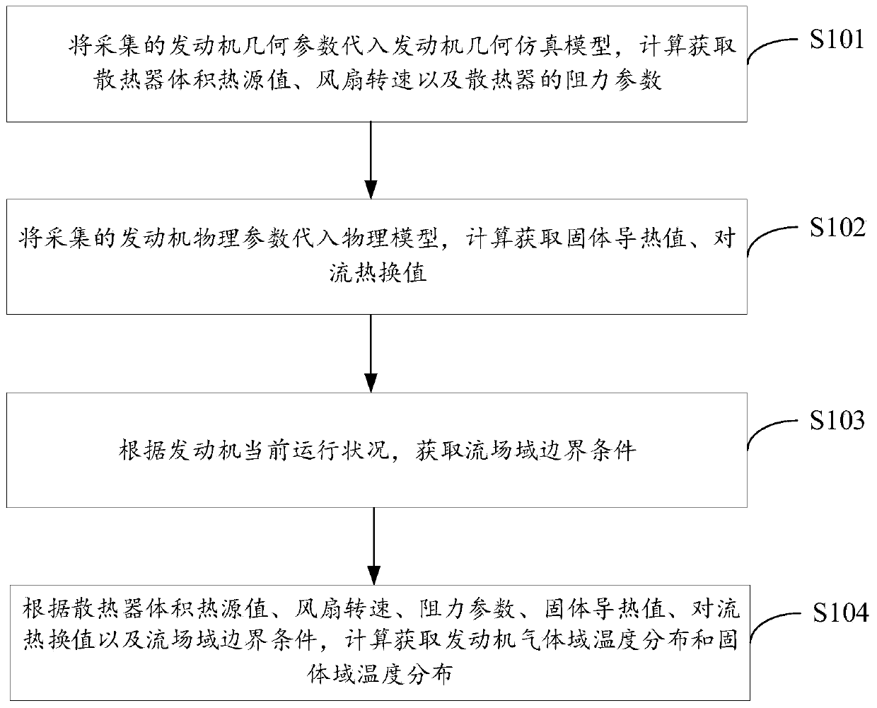
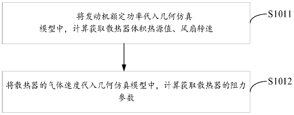
The invention provides an engine temperature distribution calculation method and device and a storage medium, and relates to the technical field of software simulation. The method comprises the following steps of substituting collected geometric parameters of the engine into a geometric simulation model of an engine, calculating to obtain a radiator volume heat source value, a fan rotating speed and resistance parameters of a radiator, substituting the collected physical parameters of the engine into a physical model, calculating to obtain a solid heat conduction value and a convective heat exchange value, and obtaining a flow field domain boundary condition according to the current operation condition of the engine; and calculating to obtain engine gas domain temperature distribution andsolid domain temperature distribution according to the radiator volume heat source value, the fan rotating speed, the resistance parameter, the solid heat conduction value, the convective heat exchange value and the flow field domain boundary condition. By calculating the mutual heat transfer effect of the gas domain and the solid domain and the solid heat transfer property of the solid domain atthe same time, accurate temperature distribution of all parts of the engine compartment can be calculated, and accurate evaluation of the positions of heat damage points of important components in anengine is achieved.

Description

technical field [0001] The present application relates to the technical field of software simulation, in particular, to a calculation method, device and storage medium for engine temperature distribution. Background technique [0002] During the working process of the engine, the combustion of gas and the overcoming of friction will generate heat. The heat absorbed by the engine will cause its own temperature to rise, and the heat will be transferred to the contacting parts through heat conduction. The engine radiator is the main equipment to reduce the engine temperature. The coolant absorbs the heat of various parts of the engine, and the radiator dissipates the heat absorbed by the coolant to the surrounding environment to achieve the purpose of reducing the engine temperature. When the heat dissipation capacity of the engine declines and the heat load is too large, the engine will overheat, resulting in a decrease in the mechanical properties of the engine parts, destroy...

Claims


Application Information

Patent Timeline
Patent Type & Authority Applications(China)
IPC IPC(8): G06F30/15G06F30/20G06F119/08
Inventor 孙天时万福来
Owner SANY HEAVY MACHINERY
Why Eureka
Try Eureka