Three-dimensional calibration plate, system and method suitable for laser 3D vision

A technology of three-dimensional calibration and calibration board, applied in the field of mechanical 3D vision, can solve the problem that the camera shooting accuracy is inversely proportional to the field of view

Pending Publication Date: 2020-07-28
深圳群宾精密工业有限公司
View PDF0 Cites 7 Cited by
  • Summary
  • Abstract
  • Description
  • Claims
  • Application Information

AI Technical Summary

Problems solved by technology

[0008] This application aims to achieve the technical effects of laser 3D vision hardware calibration, image stitching, and coordinate system conversion to solve the calibration problem that the camera shooting needs to be vertical to the X direction and the Y direction, and solve the problem that the camera shooting accuracy is inversely proportional to the field of view through image stitching. Solve the problem of fixed-point operation and shooting through coordinate system conversion, and provide a three-dimensional calibration board suitable for laser 3D vision

Method used


Image

  • Three-dimensional calibration plate, system and method suitable for laser 3D vision
  • Three-dimensional calibration plate, system and method suitable for laser 3D vision
  • Three-dimensional calibration plate, system and method suitable for laser 3D vision

Examples


Embodiment Construction

[0053] It should be understood that the specific embodiments described here are only used to explain the present application, and are not intended to limit the present application.

[0054] The technical solutions in the embodiments of the application will be clearly and completely described below in conjunction with the accompanying drawings in the embodiments of the application. Obviously, the described embodiments are only part of the embodiments of the application, not all implementations example. Based on the embodiments in this application, all other embodiments obtained by persons of ordinary skill in the art without creative efforts fall within the protection scope of this application.

[0055] It should be noted that the terms "comprising", "comprising" and "having" in the specification and claims of the present application and the above drawings and any variations thereof are intended to cover non-exclusive inclusion. For example, a process, method, system, product ...


PUM


Abstract

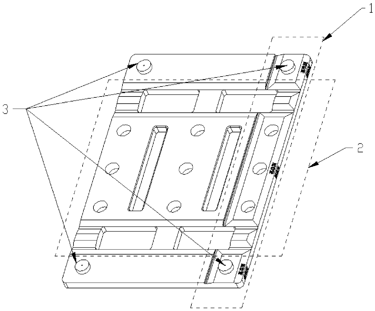
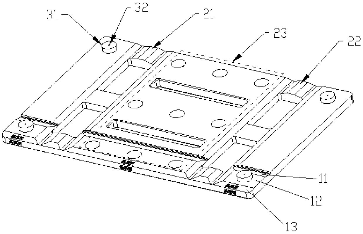
The invention provides a three-dimensional calibration plate suitable for laser 3D vision, which is an image acquisition object of a line laser scanning 3D camera and is applied to the field of mechanical 3D vision. A plate body of the calibration plate is provided with a camera reference part, a view splicing part and a coordinate positioning part. The camera reference part, the view splicing part and the coordinate positioning part are arranged, the camera calibration problem that the camera needs to be perpendicular to the height in the X direction and the Y direction during camera shootingis solved through the camera reference part, the problem that the camera shooting precision is inversely proportional to the view field is solved through image splicing, and point taking of images inactual product images is achieved through coordinate system conversion of the camera through the coordinate positioning part. The correspondence problem actually performed on the product by the device is then guided.

Description

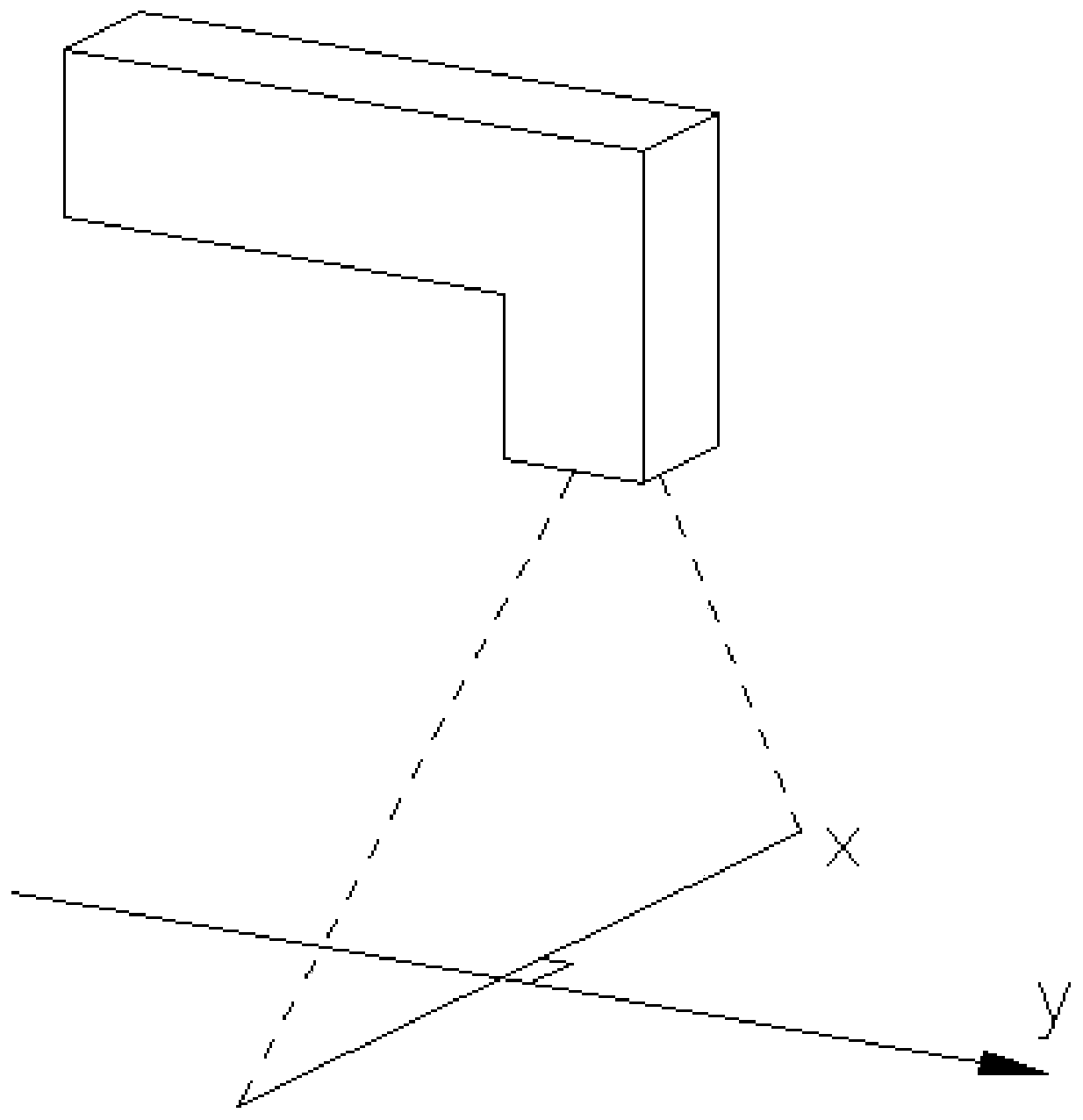
technical field [0001] This application relates to the technical field of mechanical 3D vision, in particular to a three-dimensional calibration plate suitable for laser 3D vision. Background technique [0002] The image acquisition action of the existing line laser scanning 3D camera needs to perform a linear scanning action through motion to perform continuous image acquisition of the scanned object, and then form a three-dimensional point cloud image. The image acquisition action is shown in the attached figure 1 As shown, the line laser scanning 3D camera performs precise linear motion along the Y direction; [0003] After scanning the 3D point cloud image, the image is highly consistent with the shape of the scanned object, so the scanned object can be directly processed for secondary processing, such as dimension detection, defect detection, or positioning guidance for cutting, grinding or spraying; However, when the above-mentioned line laser scanning 3D camera reali...

Claims


Application Information

Patent Timeline
Patent Type & Authority Applications(China)
IPC IPC(8): G06T7/80G06T3/40
CPCG06T3/4038G06T7/85G06T2207/10012
Inventor 姚绪松陈方
Owner 深圳群宾精密工业有限公司
Why Eureka
Try Eureka