Protection method of power line

A technology of power lines and delay circuits, which is applied in the direction of automatic disconnection emergency protection devices, circuit devices, emergency protection circuit devices, etc., can solve the problems involving many devices, long overall time consumption, and large amount of calculation, etc., to simplify data The effect of processing capacity, low cost and improving timeliness

Active Publication Date: 2020-07-28
BAODING YUXIN ELECTRICAL TECH
View PDF7 Cites 11 Cited by
  • Summary
  • Abstract
  • Description
  • Claims
  • Application Information

AI Technical Summary

Problems solved by technology

However, the process of writing and manufacturing, transmission, reception, and interpretation of messages involves many links, not only involving many devices, a large amount of calculation, but also complex algorithms, which take a long time overall and make device reliability design difficult.

Method used


Image

  • Protection method of power line

Examples


Embodiment 1

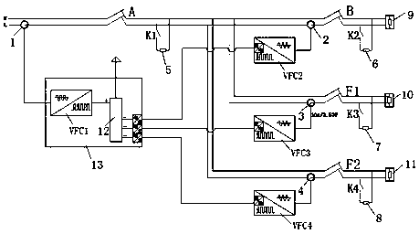
[0019] In the embodiment of the present invention, switch A and switch B are located on the main line, switch A is an electric energy inlet switch, switch B is adjacent to switch A and connected through the main line wire, and two switches are arranged on the main line between switch A and switch B. branch lines (or there may be no branch lines or other numbers of branch lines), on which switches F are respectively set. On the switch A, the current through the switch A is converted into a weak current voltage signal through the primary current transformer and the secondary current transformer, and then directly converted into a pulse quantity having a proportional relationship with the input voltage through the first voltage-frequency conversion circuit, That is to say, the pulse quantity is directly proportional to the current quantity at the switch A, and the pulse quantity is transmitted to the conversion calculation unit in real time. Similarly, the currents at the switch ...

Embodiment 2

[0025] Embodiment 2 simulation test

[0026] Power line protection is generally the protection of high-voltage distribution lines (10KV, 35KV, etc.). The simulation test will be carried out in the low-voltage line environment to verify the feasibility and effect of this method.

[0027] 1. Simulation test environment

[0028] a. LN single-phase experimental circuit environment

[0029] b. Install a current transformer 1 (10A / 3.53V) on the upper port of switch A, and connect it to the voltage-frequency converter VFC1. Before inputting the voltage-frequency converter VFC1, it is processed by a reference voltage raising circuit. The voltage-frequency converter VFC1 is theoretically the largest The pulse frequency is 500K, and the voltage-frequency converter VFC1 directly transmits the pulse point-to-point to the conversion calculation unit on the monitoring board 13 (a programmable logic controller is used, because the voltage-frequency converter VFC1 and the monitoring board 13...


PUM


Abstract

The invention discloses a protection method of a power line. An electric energy inlet switch A and a switch B adjacent to the switch A are arranged on a trunk line, a switch F is arranged on a branchline, the magnitudes of current passing through the switch A, the switch B and the switch F are converted into pulse quantities with corresponding relations respectively, and the pulse quantities aredirectly transmitted to a conversion calculation unit in a point-to-point mode, the conversion calculation unit judges whether the magnitude of current passing through the switch A is equal to the sumof the magnitude of current passing through the switch B and the magnitude of current passing through the switch F or not by calculating the pulse quantities, and if not, the switch A is cut off. According to the method, the differential principle is utilized, the processing process is greatly simplified, data processing and transmission are real-time and rapid, the number of used components is small, the process is simple, the response is more timely, and the line can be protected more rapidly.

Description

technical field [0001] The invention relates to the field of power line protection, in particular to a method for protecting a power line. Background technique [0002] Differential protection is a line protection method, and differential protection is often used between the main line and branch lines. The existing differential protection is to obtain parameters such as current and voltage at both ends of the line through the current transformer (CT), and convert them into messages and send them to the computer. Compare the current with the current at the downstream point to see if the current at the upper point is equal to the current at the lower point. If not, it is judged that a fault has occurred and the switch of the line is cut off to cut off the faulty line. However, the process of message writing and manufacturing, transmission, reception, and interpretation involves many links. Not only does it involve many devices and a large amount of calculation, but also the a...

Claims


Application Information

Patent Timeline
Patent Type & Authority Applications(China)
IPC IPC(8): H02H7/26H02H3/30
CPCH02H7/263H02H3/305
Inventor 薛占钰王建升刘建伟
Owner BAODING YUXIN ELECTRICAL TECH
Why Eureka
Try Eureka