
Temperature-drift-resistant frequency-stabilized pulse generation electronic chip and voltage regulation chip

A technology for voltage regulation chips and pulse generation, which is applied in the direction of pulse generation, pulse technology, and electric pulse generation. It can solve the problems of poor universality, limited application range, and rounded corners of the output waveform, and achieve enhanced work reliability. The effect of simple circuit structure and wide application range

Inactive Publication Date: 2020-07-28
佛山中锦微电科技有限公司
View PDF0 Cites 0 Cited by
  • Summary
  • Abstract
  • Description
  • Claims
  • Application Information

AI Technical Summary

Problems solved by technology

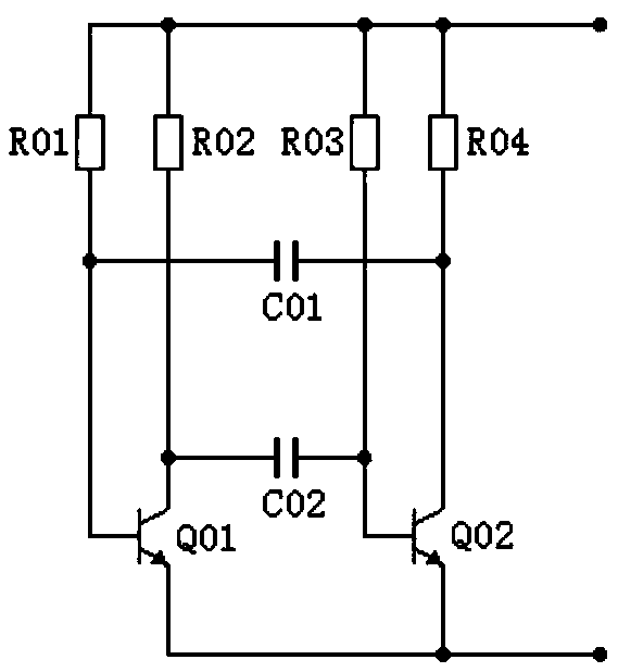
[0002] In a variety of common electronic circuits, a pulse generator is often used, and its frequency is often affected by factors such as temperature. The actual measurement shows that the frequency stability of the general transistor oscillation circuit is poor, such as the common dual-tube multivibrator circuit. The frequency in the range of ~125°C changes by 4 to 10 times, and there are very few chips with dedicated stable frequency output.
In addition, the conventional transistor oscillator circuit also has the problem that the output waveform often has rounded corners, which limits its application range.
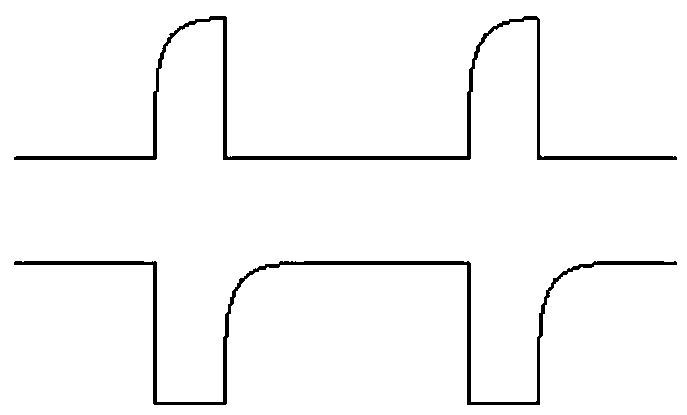
[0003] In common transistor oscillator circuits, such as figure 1 As shown, two triodes Q01, Q02 and R01~R04, C01, C02 form a multivibrator, and the output waveform of the collector of Q01 or Q02 is as follows: figure 2 As shown, it can be seen that there are rounded corners, the waveform is irregular, many occasions cannot meet the design requirements, and the stable output of the duty cycle is difficult to reach the range below 5% or above 95%, so the application of this oscillator is greatly limited.

Method used


Image

  • Temperature-drift-resistant frequency-stabilized pulse generation electronic chip and voltage regulation chip
  • Temperature-drift-resistant frequency-stabilized pulse generation electronic chip and voltage regulation chip
  • Temperature-drift-resistant frequency-stabilized pulse generation electronic chip and voltage regulation chip

Examples


Embodiment 1

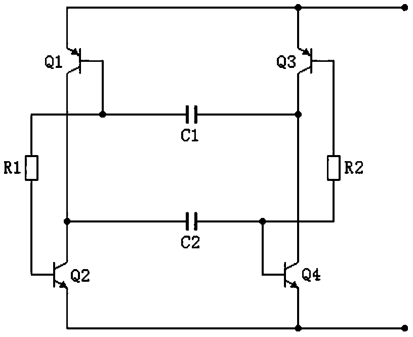
[0054] like image 3 As shown, the chip includes a first transistor Q1, a second transistor Q2, a third transistor Q3, a fourth transistor Q4, a first capacitor C1, a second capacitor C2, a first bias resistor R1 and a second bias resistor R2,

[0055] The first transistor and the second transistor are paired transistors with complementary polarities. From the perspective of the DC path, the two transistor structures constitute the first arm.

[0056] The third transistor and the fourth transistor also serve as paired transistors with complementary polarities. Similarly, the two transistor structures form the second arm in the view of the DC path.

[0057] The first arm and the second arm are configured in the following connection relationship:

[0058] The collector of the first transistor is connected to the collector of the second transistor as the output terminal of the first arm,

[0059] The collector of the third transistor is connected to the collector of the fourth ...

Embodiment 2

[0081] like Figure 5 As shown, the chip includes a first transistor Q1, a second transistor Q2, a third transistor Q3, a fourth transistor Q4, a first capacitor C1, a second capacitor C2, a resistor R1, a resistor R2 and a resistor R3,

[0082] The first transistor and the second transistor form a first arm as a pair of transistors with complementary polarities,

[0083] The third transistor and the fourth transistor form a second arm as a pair of transistors with complementary polarities,

[0084] The first arm and the second arm are configured in the following connection relationship:

[0085] The collector of the first transistor is connected to the collector of the second transistor as the output terminal of the first arm,

[0086] The collector of the third transistor is connected to the collector of the fourth transistor as the output end of the second arm,

[0087] One end of the resistor R1 is connected to one end of the resistor R2 and the connection point of the ...

Embodiment 3

[0100] The voltage regulation chip, such as Figure 7 As shown, it includes the frequency stable pulse generation electronic chip with temperature drift resistance described in the first aspect of the implementation mode of the present invention, and also includes a sampling unit, a threshold unit, a comparison unit, a trigger unit and a power unit,

[0101] The sampling unit and the threshold unit are connected to the comparison unit, and are used to compare the output signal of the sampling unit with the reference voltage determined by the threshold unit in the comparison unit, and the trigger unit is a flip-flop,

[0102] The output terminal of the comparison unit is connected to the trigger unit, the output terminal of the trigger unit is connected to the input terminal of the power unit, the output terminal of the power unit is used to control the current of the excitation winding of the generator, and the narrow pulse output terminal of the frequency stable pulse generati...


PUM


Abstract

A temperature-drift-resistant frequency-stabilized pulse generation electronic chip belongs to the technical field of electronics and automobile control and comprises a first transistor, a second transistor, a third transistor, a fourth transistor, a first capacitor, a second capacitor, a first bias resistor and a second bias resistor. The first transistor and the second transistor are geminate transistors to form a first arm, the third transistor and the fourth transistor are geminate transistors to form a second arm, collectors of the first transistor and the second transistor are connectedto form a first arm output end, collectors of the third transistor and the fourth transistor are connected to form a second arm output end, a first bias resistor is serially connected between bases ofthe first transistor and the second transistor, and a second bias resistor is serially connected between the third transistor and the fourth transistor; emitters of the first transistor and the thirdtransistor are connected with a positive electrode of a power supply; emitters of the second transistor and the fourth transistor are connected with the negative electrode of the power supply; the first capacitor is connected with the second arm output end and the first transistor base; the second capacitor is connected with the first arm output end and the fourth transistor base; and due to consistent parameters and offset of temperature drift, the first arm outputs frequency-stable and temperature-resistant first polarity narrow pulses, and the second arm outputs frequency-stable and temperature-resistant second polarity narrow pulses with opposite polarities.

Description

technical field [0001] The invention belongs to the technical field of electronics and automobile control, and in particular relates to a frequency-stabilized pulse generation electronic chip and a voltage regulation chip resistant to temperature drift. Background technique [0002] In a variety of common electronic circuits, a pulse generator is often used, and its frequency is often affected by factors such as temperature. The actual measurement shows that the frequency stability of the general transistor oscillation circuit is poor, such as the common dual-tube multivibrator circuit. The frequency in the range of ~125°C changes by 4 to 10 times, and there are very few chips with dedicated stable frequency output. In addition, conventional transistor oscillating circuits also have the problem that output waveforms often have rounded corners, which limits their application range. [0003] In common transistor oscillator circuits, such as figure 1 As shown, two triodes Q01...

Claims


Application Information

Patent Timeline
Patent Type & Authority Applications(China)
IPC IPC(8): H03K3/011
CPCH03K3/011
Inventor 杨明
Owner 佛山中锦微电科技有限公司
Learn More