
Eureka
For R&D, Eureka makes reading and utilizing patents & technical documents easy.
Eureka AIR
Designed for self-driven R&D workflows. Generate viable solutions, solve complex R&D challenges, empower your innovation with AI.

Eureka Materials
Designed for material experts only. Revolutionize your material R&D, from search, analyze, to developing new materials.

TechResearch
Generate reliable direction feasibility study reports for your R&D in just a few steps.

TechSeek
Discover and master advanced knowledge NOW. Basics, ideas, possibilities, all at once.

TechMind
As an expert in R&D Theories, TechMind can generates customized viable solutions instantly.

TechRisk
Analyze your overall solution with one click, know your potential R&D risks in advance.

TechMonitor
Get weekly tech updates, stay abreast of the latest tech innovations and key insights.
Ventilation structure based on heat pipe radiator high-power power conversion device
A technology of power conversion device and heat pipe radiator, which is applied in the modification of power electronics, structural parts of electrical equipment, cooling/ventilation/heating transformation, etc., can solve the problem of single heat dissipation and ventilation structure, difficulty in heat dissipation and ventilation structure adjustment, economy and time Loss and other issues, to achieve the effect of increasing the connection, speeding up the air output, and increasing the air output
- Summary
- Abstract
- Description
- Claims
- Application Information
AI Technical Summary
Problems solved by technology
Method used
Image

Examples
Embodiment 1
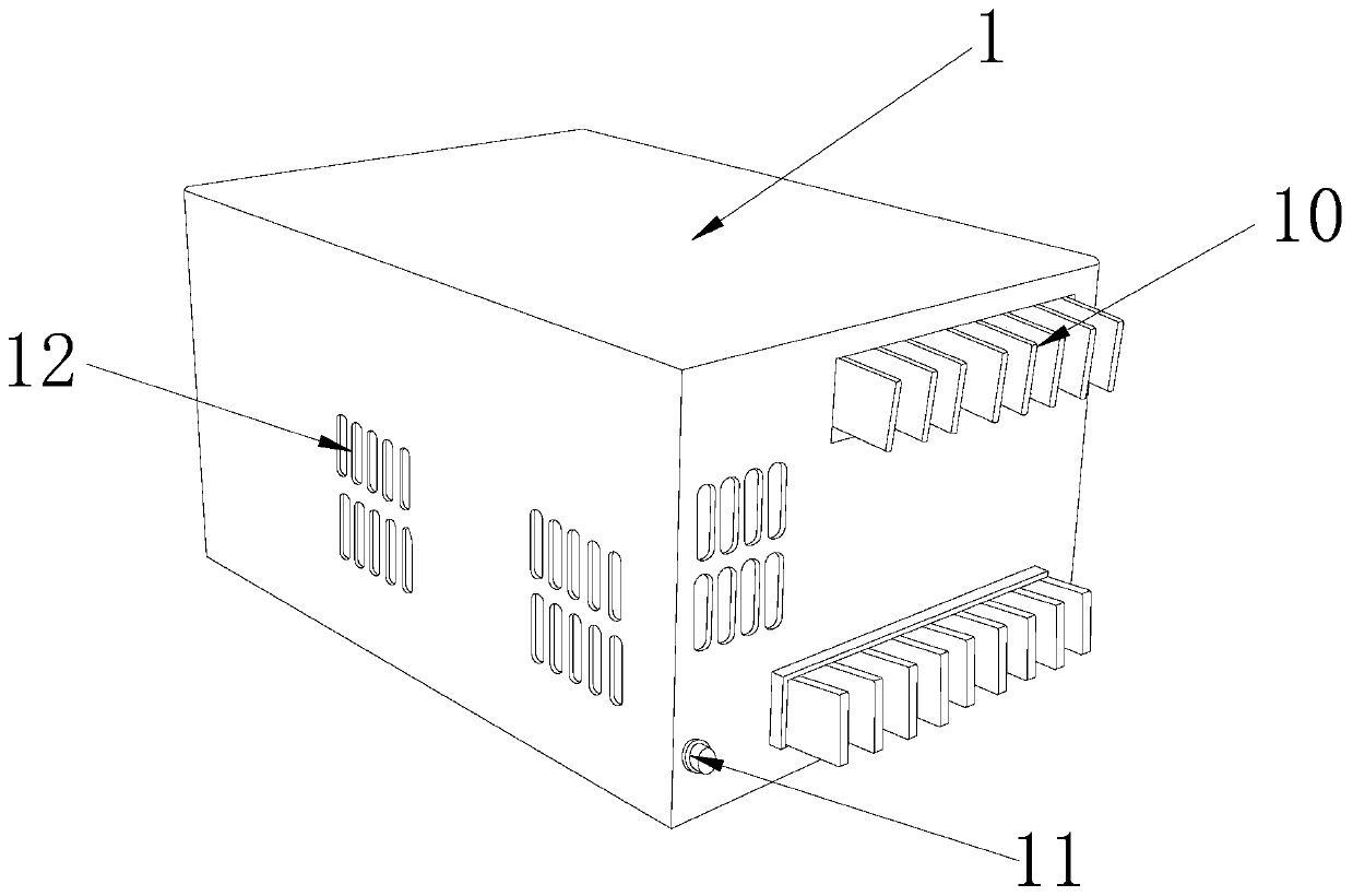
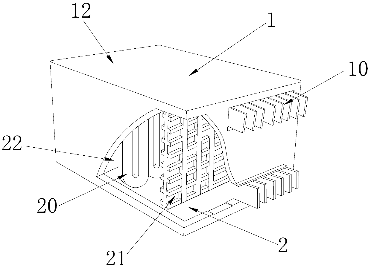
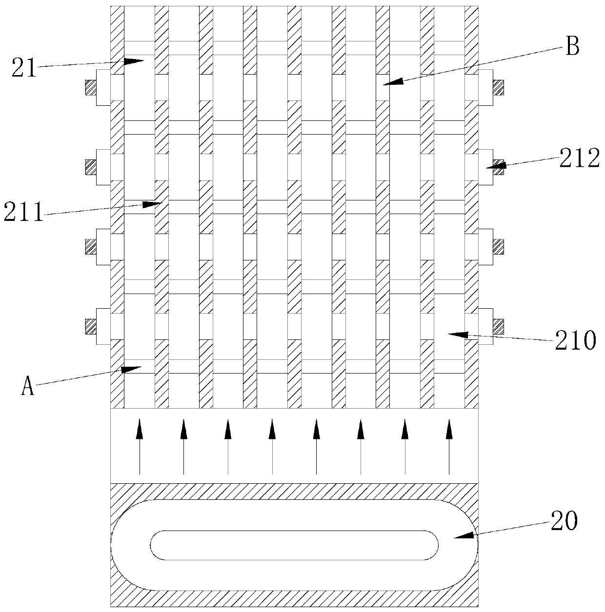
[0029] Embodiment 1: When in use, the controller 22 drives the refrigerating plate 211 on the fast ventilation plate 21 for cooling, and at the same time drives the transmission partition A to conduct air guiding work, and guides the hot air generated by the heat pipe 20 to the open air through the ventilation channel 210. In the mouth connector 212, then be connected with the ventilation hole 12 by the open connector 212, make the hot air after being cooled by the cooling plate 211, then lead out by the open connector 212, the wind force temperature of derivation is reduced; When passing through the air passage 210, the fan wing A2 is driven to rotate by the rotating shaft A1 on the transmission partition A, so that the wind force is transmitted to each other inside the air passage 210; at the same time, it is connected to the air passage 210 through the connecting hole B to avoid a When the ventilation duct 210 is blocked or the transmission partition A is broken, the rapid v...
Embodiment 2
[0030] Embodiment 2: When the wind cooled by the cooling plate 211 is sent to the open joint 212 through the connection hole B, the wind enters the air outlet C, and then is sent to the ventilation hole 12 through the conical air outlet C1, and passes through the ventilation hole 12 When it is necessary to carry out multiple ventilation holes 12 to discharge the air, it is only necessary to connect the open connector 212 and the ventilation holes 12 through the pipeline to increase the strength of the wind. The wind speed and air volume are larger when the air is out, so the intensity of heat dissipation is enhanced, and at the same time, the adjustment of the heat dissipation and air outlet structure is convenient.
[0031] The technical progress that the present invention obtains relative to the prior art is:
[0032] 1. Cool the hot air generated by the heat pipe through the cooling plate on the fast ventilation plate, and then drive the fan fins to guide the air through th...
PUM
 Abstract
Description
Claims
Application Information
 - R&D Engineer
- R&D Manager
- IP Professional
- Industry Leading Data Capabilities
- Powerful AI technology
- Patent DNA Extraction
Browse by: Latest US Patents, China's latest patents, Technical Efficacy Thesaurus, Application Domain, Technology Topic, Popular Technical Reports.
© 2024 PatSnap. All rights reserved.Legal|Privacy policy|Modern Slavery Act Transparency Statement|Sitemap|About US| Contact US: help@patsnap.com