Automatic paint spraying equipment for pickaxe

An automatic painting and pickaxe technology, applied in the direction of the spraying device, can solve the problems of flying everywhere, affecting the surrounding environment, needing to turn the pickaxe, etc., to achieve the effect of avoiding rotation

Active Publication Date: 2020-07-31
赣州圣享区块链技术有限公司
View PDF10 Cites 16 Cited by
  • Summary
  • Abstract
  • Description
  • Claims
  • Application Information

AI Technical Summary

Problems solved by technology

[0004] In order to overcome the disadvantages of moving the painting tool back and forth for painting, it is laborious, and it is troublesome to flip the pick. After the paint is atomized, it is sprayed everywhere and affects the surrounding environment. The technical probl

Method used


Image

  • Automatic paint spraying equipment for pickaxe
  • Automatic paint spraying equipment for pickaxe
  • Automatic paint spraying equipment for pickaxe

Examples


Embodiment 1

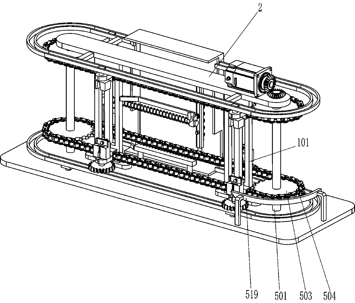
[0022] see Figure 1-Figure 5 , a kind of pick automatic painting equipment, including a base plate 1, a support plate 101, a frame 2, a servo motor 3, a first bevel gear 4, a moving assembly 5 and a painting assembly 6, and the middle parts of the front and rear sides of the top of the base plate 1 are fixed. There is a support plate 101, and the frame 2 is fixedly connected between the tops of the support plates 101 on the front and rear sides. The front side of the top of the frame 2 is connected with a servo motor 3 by means of bolts, and the output shaft of the servo motor 3 is connected by a coupling. There is a first bevel gear 4, a mobile assembly 5 that can place a pick between the top of the bottom plate 1 and the frame 2, and a painting assembly 6 on the rear support plate 101, which cooperates with the mobile assembly 5.

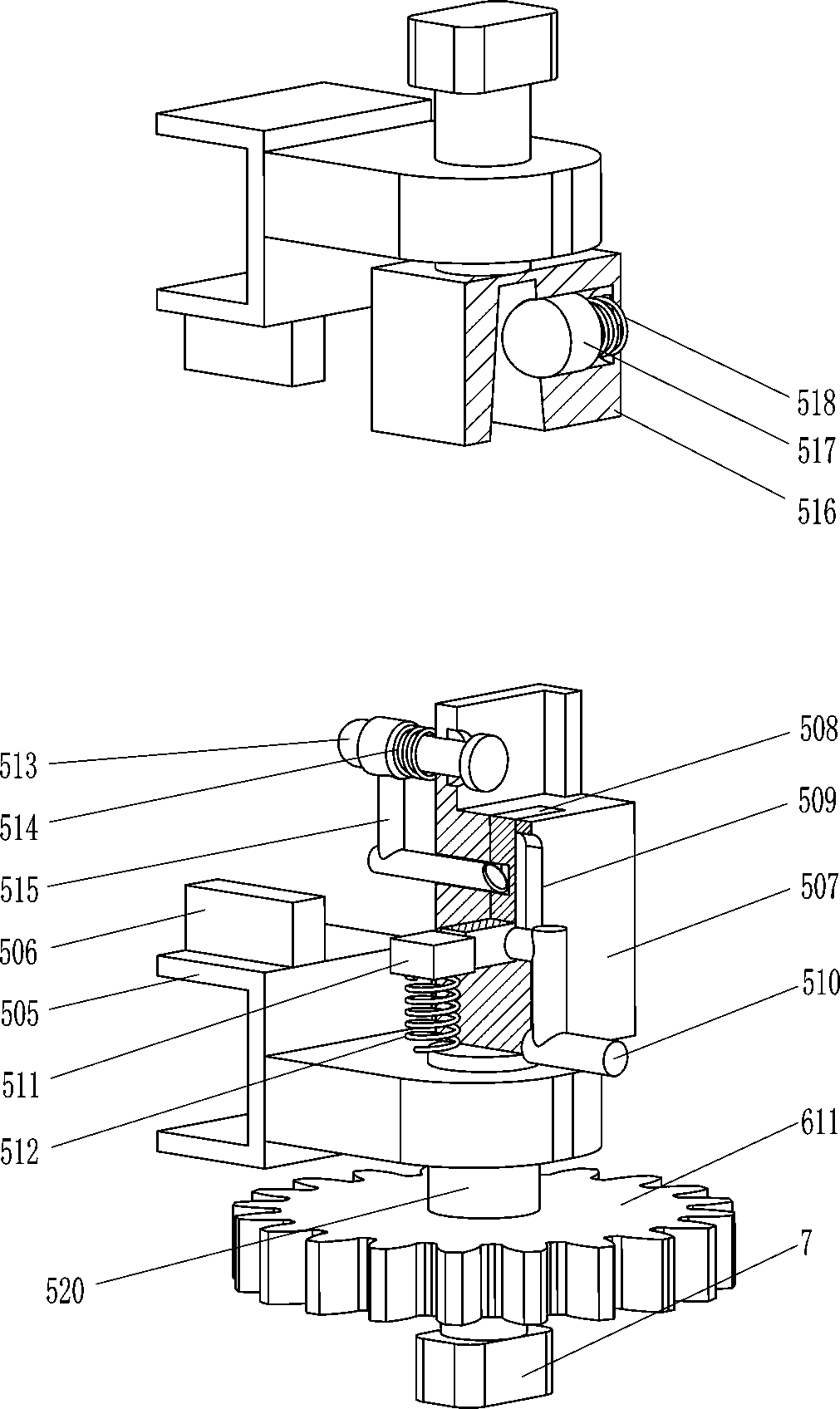
[0023]The moving assembly 5 includes a rotating shaft 501, a second bevel gear 502, a sprocket 503, a chain 504, a mounting block 505, a pushing...

Embodiment 2

[0029] see figure 1 , image 3 and Figure 4 The main difference between this embodiment and embodiment 1 is that in this embodiment, a guide block 7, a first guide rail 8 and a second guide rail 9 are also included, and the outer surface of the frame 2 is circumferentially fixed with a second guide rail. rail 9, the top of the bottom plate 1 is fixedly connected with the first guide rail 8, the first guide rail 8 is located below the chain 504, and the outer ends of the upper and lower sides of the rotating rod 520 are fixedly connected with the guide block 7, and the lower guide block 7 and the first guide rail 8, and the upper guide block 7 cooperates with the second guide rail 9.

[0030] When the installation block 505 drives the rotating rod 520 to reverse, the rotating rod 520 reverses and also drives the guide block 7 to reverse, and then after the pick painting is completed, the guide block 7 also reverses to the first guide rail 8 and the second guide rail 9, when...


PUM


Abstract

The invention relates to paint spraying equipment, in particular to automatic paint spraying equipment for a pickaxe. The invention aims at solving the technical problem of how to design the automaticpaint spraying equipment for the pickaxe, which can comprehensively spray paint on the pickaxe without the need of manpower, is effort-saving and convenient, and can prevent flying oil paint from influencing the ambient environment. The automatic paint spraying equipment for the pickaxe comprises a bottom plate and a servo motor, wherein support plates are symmetrically and fixedly connected to one side of the bottom plate; a rack is fixedly connected between the end parts, far away from the bottom plate, of the two support plates; and the servo motor is arranged on one side, far away from the bottom plate, of the rack. According to the automatic paint spraying equipment for the pickaxe provided by the invention, the pickaxe is fixed through a pickaxe moving block and a second clamp rod,and the servo motor is started to rotate forwards, so that the pickaxe can be rotated inversely so as to spray the paint through a paint spraying part; and in addition, through the cooperation of a rotary gear and a rack, the pickaxe is rotated so as to be sprayed with the paint comprehensively and has no need to be sprayed with the paint manually, so that the automatic paint spraying equipment for the pickaxe is effort-saving and convenient.

Description

technical field [0001] The invention relates to a painting equipment, in particular to a pickaxe automatic painting equipment. Background technique [0002] A common tool, generally a long wooden handle, with an iron head, T-shaped as a whole, resembling a pickaxe, with a pointed end and a flat shovel-like end. It has a wide range of uses, large ones can be used to break and destroy hard ground, small ones can be used as portable tools, and are generally used for outdoor activities. When the pickaxes are made, in order to make them more beautiful and avoid corrosion, they will Spray paint to protect the pickaxe. [0003] At present, most of the pickaxes are painted by multiple people. First, the pickaxe needs to be placed on a designated position, and then the paint is sprayed on the pickaxe with a painting tool in hand. Since it is necessary to move the painting tool back and forth for painting, it is more laborious. , and it is necessary to constantly turn the pick back ...

Claims


Application Information

Patent Timeline
IPC IPC(8): B05B13/02B05B13/04B05B12/32
CPCB05B13/0228B05B13/0405B05B12/32
Inventor 钟鸿佛
Owner 赣州圣享区块链技术有限公司
Why Eureka
Try Eureka