Coating raw material feeding bin

A technology for feeding bins and raw materials, which is applied in the direction of filters, grids, mixers, etc., can solve the problems of low coating production quality and uncontrolled particle size, and achieve the effects of improving product quality, avoiding insufficient dissolution, and avoiding precipitation

Inactive Publication Date: 2020-07-31
张家界荣丰科技发展有限公司
View PDF1 Cites 1 Cited by
  • Summary
  • Abstract
  • Description
  • Claims
  • Application Information

AI Technical Summary

Problems solved by technology

[0004] The present invention provides a coating raw material feeding bin to solve the problem in the prior art that the production quality of the coating obtained is low due to the failure to control the particle size of the powder before mixing

Method used


Image

  • Coating raw material feeding bin
  • Coating raw material feeding bin
  • Coating raw material feeding bin

Examples


Embodiment Construction

[0023] In order to make the technical means, creative features, goals and functions achieved by the present invention clearer and easier to understand, the present invention will be further elaborated below in conjunction with the accompanying drawings and specific embodiments:

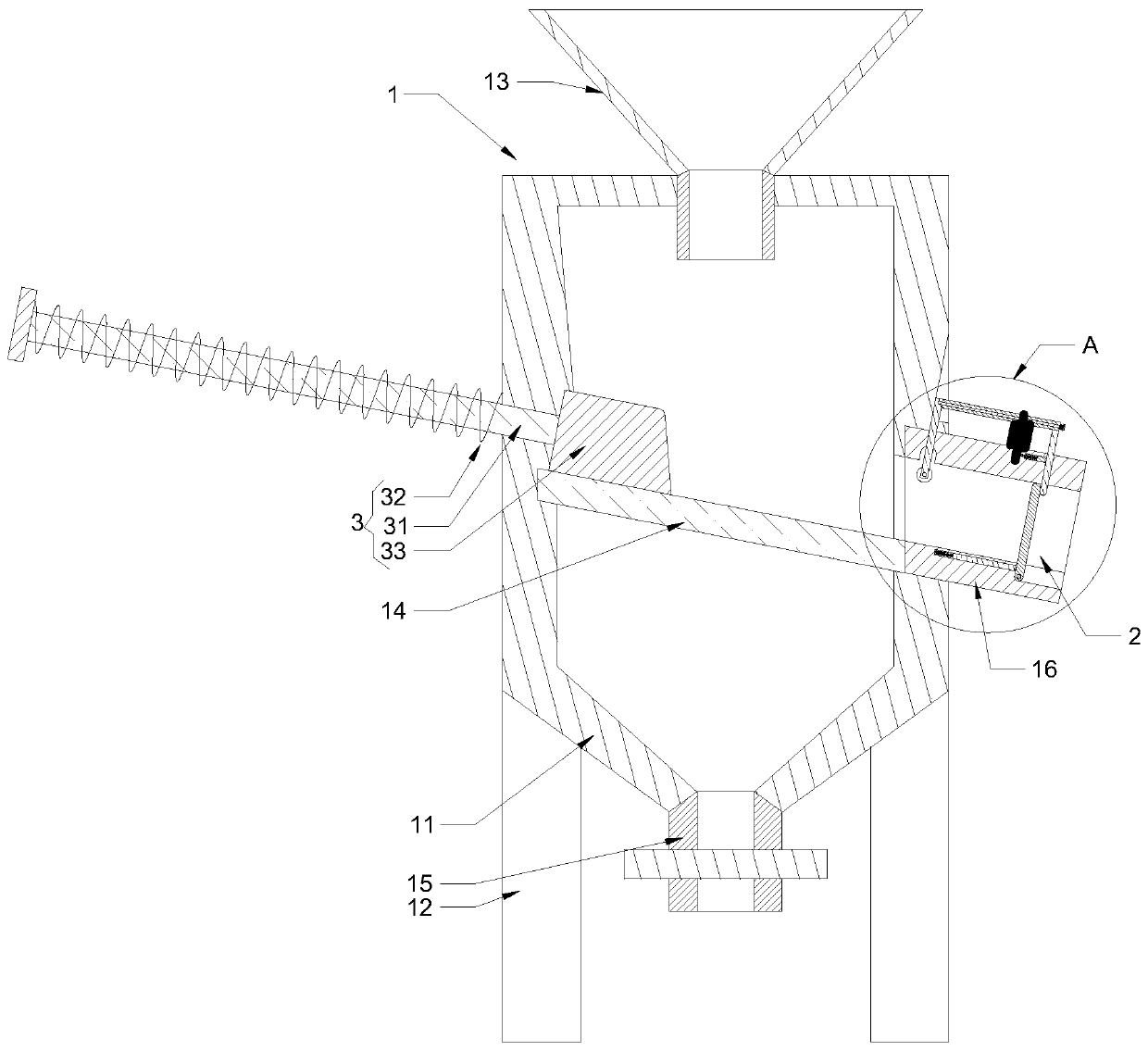
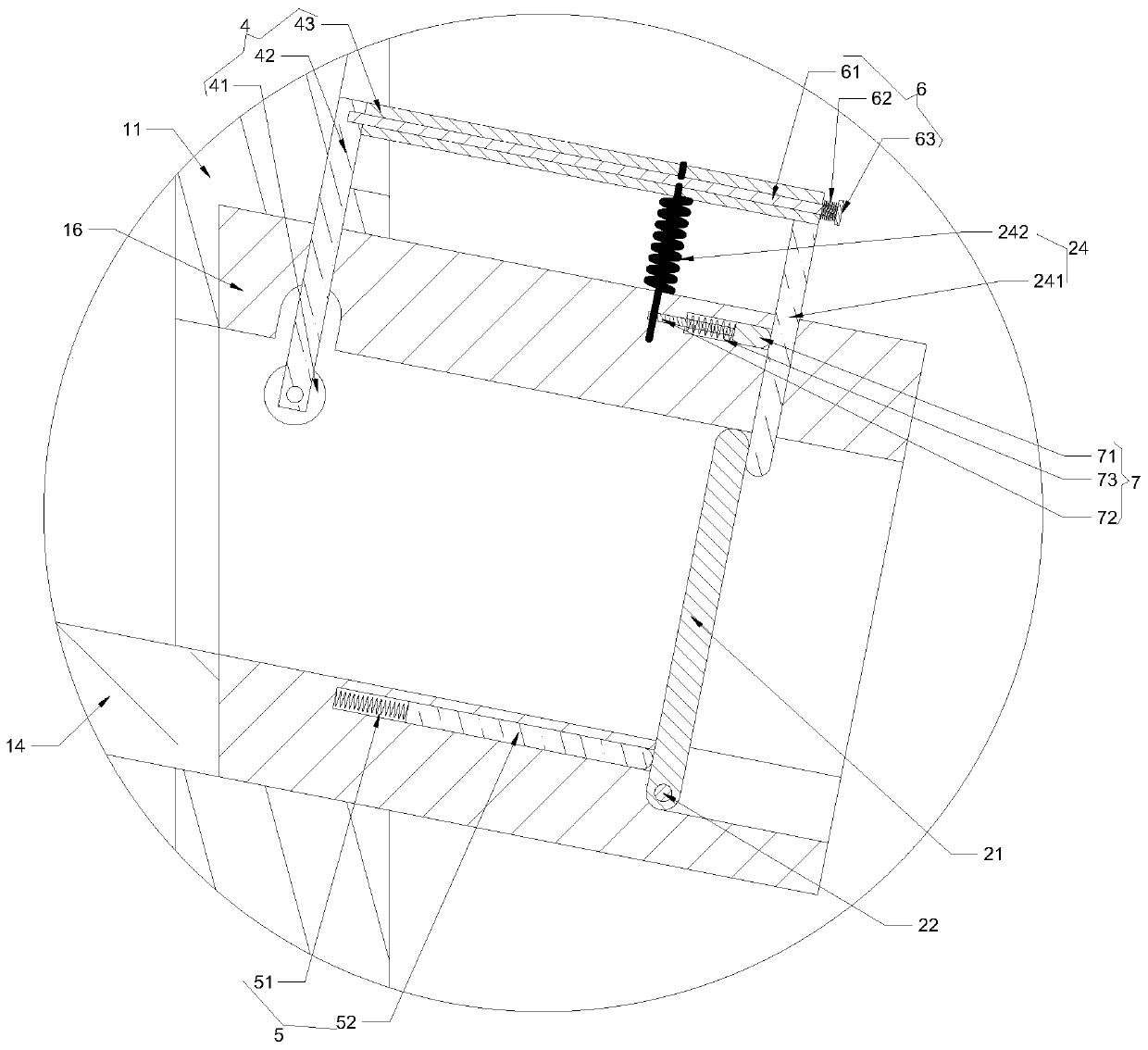
[0024] like Figure 1 to Figure 3 As shown, the present invention proposes a kind of coating raw material feeding bin, comprises: separation device 1, and it comprises: separation case 11, stand 12, hopper 13, filter screen 14 and first discharge pipe 15, separation case 11 passes vertical The frame 12 stands on the ground, and a cavity is provided in the separation box 11, and a filter screen 14 is installed on the cavity inwall, and the filter screen 14 divides the cavity into an upper cavity and a lower cavity, and the upper cavity is located above the lower cavity, and the filter screen 14 is arranged on the separation box. A hopper 13 communicating with the upper chamber is installed on the top o...


PUM


Abstract

The invention provides a coating raw material feeding bin. The coating raw material feeding bin comprises a separating device, a feeding pump and a bin body. The separating device comprises a separating box, a vertical frame, a hopper, a filter screen and a first discharging pipe. The separating box is erected on the ground through the vertical frame, and a cavity is formed in the separating box.The filter screen is installed on the inner wall of the cavity and further divides the cavity into an upper cavity body and a lower cavity body. The upper cavity body is located above the lower cavitybody. The hopper communicating with the upper cavity body is installed at the top of the separating box, and the first discharging pipe is installed at the bottom of the separating box and further communicates with the lower cavity body. The filter screen only allows fine powder to pass through. The input end of the feeding pump communicates with the bottom end of the first discharging pipe. Thebin body communicates with the output end of the feeding pump. The coating raw material feeding bin solves the problem that obtained coatings are low in production quality due to the fact that the powder particle size is not controlled before mixing in the prior art.

Description

technical field [0001] The invention relates to equipment for coating production, in particular to a coating raw material feeding bin. Background technique [0002] The Chinese patent discloses a feeding device for industrial paint production with the application number CN201720039831.9, which includes a dispersion kettle, an outlet pipe with a solenoid valve at the bottom of the dispersion kettle, a stirring paddle in the dispersion kettle, and a seal at the top of the dispersion kettle. Cover, the sealing cover is provided with a powder feeding device, a liquid material feeding device and an exhaust device; the powder feeding device includes a powder bin, and the bottom of the powder bin communicates with the corresponding hole on the sealing cover through a pipeline with a solenoid valve; The liquid feeding device includes a buffer silo, the lower end of the buffer silo communicates with the corresponding hole on the sealing cover, and at least two liquid material inlets ...

Claims


Application Information

Patent Timeline
IPC IPC(8): B07B1/04B07B1/46B07B1/52B01F15/02
CPCB07B1/04B07B1/46B07B1/526B01F35/71705B01F35/71
Inventor 李阳辛超
Owner 张家界荣丰科技发展有限公司
Why Eureka
Try Eureka