A self-cleaning stopper for underground garage

An underground garage and limiter technology, which is applied to building types, buildings where cars are parked, buildings, etc., can solve problems such as serious friction between warning tubes and wheels, and reflective signs are easily polluted.

Active Publication Date: 2021-07-30
聊城市四方泰和商务信息咨询有限责任公司
View PDF5 Cites 0 Cited by
  • Summary
  • Abstract
  • Description
  • Claims
  • Application Information

AI Technical Summary

Problems solved by technology

[0005] The purpose of the present invention is to solve the problem of serious friction between the existing warning tube and the wheel, and the problem that the reflective signs are easily polluted, to provide a rotatable warning tube to reduce friction with the wheel and to clean the warning tube by using airflow Self-cleaning underground garage limiter

Method used


Image

  • A self-cleaning stopper for underground garage
  • A self-cleaning stopper for underground garage
  • A self-cleaning stopper for underground garage

Examples


Embodiment 1

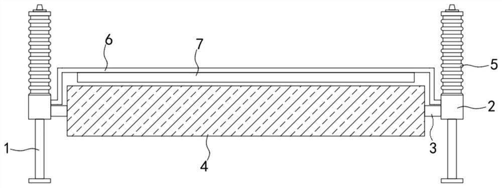
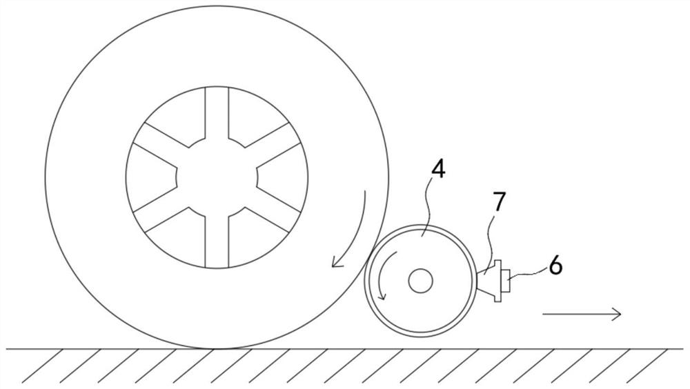
[0027] Such as Figure 1-3 As shown, a self-cleaning underground garage limiter includes two slide bars 1, which are installed side by side and horizontally on the ground, and the direction of the slide bars 1 is consistent with the driving direction of the car; 2 is slidably connected to the slider 1. Specifically, the slider 2 can be made of rubber material, which can improve the wear resistance of the slider 2, and at the same time can improve the air tightness between the slider 2 and the slider 1, reducing impurities or Dust enters the gap between the slider 2 and the slider 1 to ensure that the slider 2 slides well; the fixed shaft 3 is fixedly connected between the two sliders 2, and the fixed shaft 3 is vertical to the slider 1 , that is, the fixed shaft 3 is perpendicular to the driving direction of the vehicle; the warning tube 4 is sleeved on the fixed shaft 3 in rotation, and the surface of the warning tube 4 is provided with a warning sign, which can be painted wi...

Embodiment 2

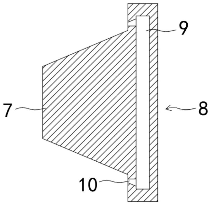
[0035] Such as Figure 4-5 As shown, the difference between this embodiment and Embodiment 1 is that: the sliding rod 1 is also covered with a reinforced corrugated sleeve 11, and the reinforced corrugated sleeve 11 can adopt the same structure as the elastic corrugated sleeve 5, that is, the materials and functions of the two The functions are the same, the reinforced corrugated sleeve 11 and the elastic corrugated sleeve 5 are installed on both sides of the slider 2 one after the other, the reinforced corrugated sleeve 11 and the elastic corrugated sleeve 5 communicate with the connecting pipe 6 through the integration mechanism 12 at the same time, and the integration mechanism 12 It includes a main pipe 13 communicated with the connecting pipe 6, and two branch pipes 14 for one-way air intake are communicated with the main pipe 13, and the two branch pipes 14 communicate with the reinforced bellows sleeve 11 and the elastic bellows sleeve 5 respectively.

[0036]By setting...


PUM


Abstract

The invention belongs to the field of construction, and in particular relates to a self-cleaning underground garage limiter, which comprises two sliding bars, which are installed side by side and horizontally on the ground; a sliding block, which is slidably connected to the sliding bar; shaft, the fixed shaft is fixedly connected between the two sliders, and the fixed shaft is set vertically to the sliding rod; the warning tube is set on the fixed shaft in rotation; two elastic corrugated sleeves, each elastic corrugated sleeve is respectively sleeved on each slide On the rod, the two ends of the elastic corrugated sleeve are sealed, and the elastic corrugated sleeve is provided with an air inlet nozzle; the connecting pipe is arranged on the rear side of the warning tube in the shape of a few characters, and the two ends of the connecting pipe are respectively connected with the two elastic corrugated sleeves. Connected; the brush strip is fixedly connected to the connecting pipe, and the brush strip is in contact with the side wall of the warning tube. In the present invention, by setting the warning tube, when the wheel is in contact with the warning tube, it will roll relative to the warning tube, reducing the friction between the wheel and the warning tube, thereby avoiding more wear on the surface of the warning tube.

Description

technical field [0001] The invention belongs to the field of construction, and in particular relates to a self-cleaning stopper for an underground garage. Background technique [0002] In order to better plan and manage parking spaces, stoppers are usually set on the parking spaces to limit the parking range of vehicles. Since underground garages are mostly set on the first or second floor of the basement, the lighting is poor, and lighting equipment is completely used for lighting. As a result, the reflective marks on the limiter are particularly important, and since the existing parking spaces are usually arranged in multiple rows, once the reflective marks of the limiter are not obvious, it is easy to hit the limiter or even cross the parking space , will cause certain damage to the vehicle body and the limiter, and there is also a greater potential safety hazard. [0003] The existing stoppers are generally fixedly installed on the parking space, and their structure is ...

Claims


Application Information

Patent Timeline
Patent Type & Authority Patents(China)
IPC IPC(8): E04H6/42
CPCE04H6/426
Inventor 耿辉徐超
Owner 聊城市四方泰和商务信息咨询有限责任公司
Why Eureka
Try Eureka