
Opposite free piston engine with combustion chambers

A piston engine and combustion chamber technology, applied in the field of range extenders, can solve problems such as increased design difficulty, reduced engine service life, and impact on reliability, so as to improve running time and service life, accelerate air circulation speed, and accelerate heat the emanating effect of

Active Publication Date: 2020-07-31
UNIV OF ELECTRONICS SCI & TECH OF CHINA ZHONGSHAN INST
View PDF6 Cites 0 Cited by
  • Summary
  • Abstract
  • Description
  • Claims
  • Application Information

AI Technical Summary

Problems solved by technology

For the single-cylinder single-piston scheme, a rebound device is needed to start the next cycle after the piston does work, which affects reliability; for the opposed-piston single-cylinder scheme, it has the disadvantages of complicated control and difficult control of inner and outer dead centers; for single-piston double-piston For the cylinder scheme, since both sides of the piston will be subjected to high temperature, the requirements for material resistance and strength are relatively high, and the technical difficulty is relatively large; for the double-piston and double-cylinder scheme, since a connecting rod device is required between the two pistons to realize mechanical linkage, the distance is relatively large. Far away, the heat dissipation system cannot be shared, and the suction pipe and exhaust pipe need to be configured separately, which increases the difficulty of design
[0003] For the existing free-piston engine, the heat generated during engine operation cannot be dissipated in time, resulting in the engine running in a high-temperature environment for a long time, the running stability of the engine cannot be effectively guaranteed, and the service life of the engine will be reduced

Method used


Image

  • Opposite free piston engine with combustion chambers
  • Opposite free piston engine with combustion chambers
  • Opposite free piston engine with combustion chambers

Examples


Embodiment Construction

[0025] In order to make the object, technical solution and advantages of the present invention clearer, the present invention will be further described in detail below in combination with specific embodiments and with reference to the accompanying drawings. It should be understood that these descriptions are exemplary only, and are not intended to limit the scope of the present invention. Also, in the following description, descriptions of well-known structures and techniques are omitted to avoid unnecessarily obscuring the concept of the present invention.

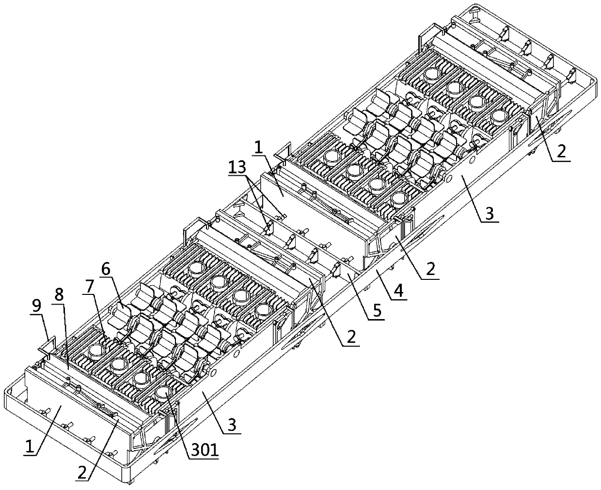
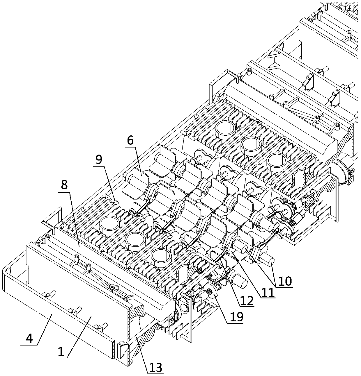
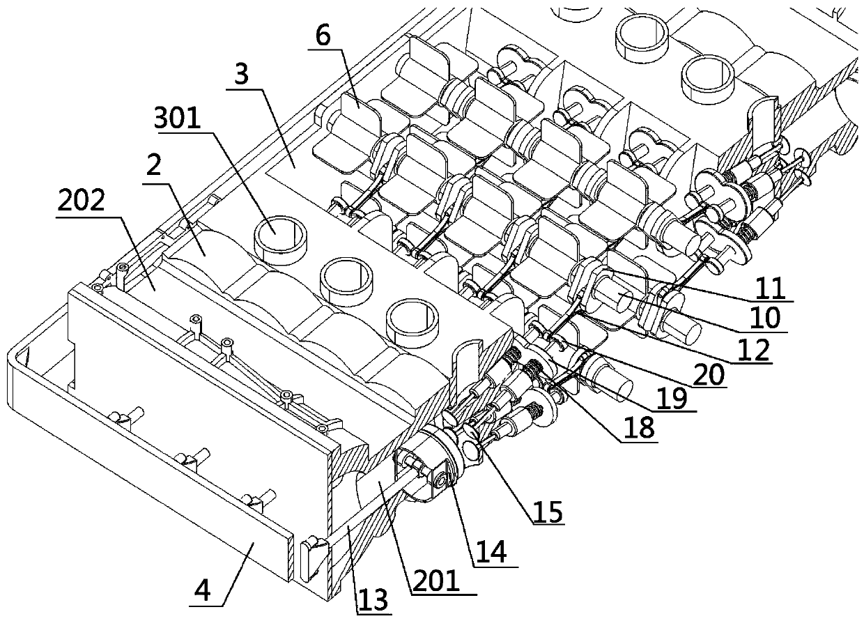
[0026] Such as Figure 1-5 As shown, a kind of opposed combustion chamber free piston engine proposed by the present invention includes an engine body and a cooling assembly;

[0027] The heat dissipation assembly includes a fan mechanism 6, a heat dissipation grid plate 7, a cooling box 8, a cooling pipe 9, an installation shaft 10, a crank 11 and a connecting rod 12; the fan mechanism 6 and the crank 11 are all arrange...


PUM


Abstract

The invention discloses an opposite free piston engine with combustion chambers. The opposite free piston engine with the combustion chambers comprises an engine body and a heat dissipation assembly,wherein the heat dissipation assembly comprises fan mechanisms, heat dissipation grid plates, cooling boxes, cooling pipes, mounting shafts, cranks and connecting rods; the plurality of fan mechanismsand the cranks are both alternately arranged on the mounting shafts in the transverse direction; two ends of the connecting rods are rotatably connected with the cranks and the power output end of the engine body correspondingly; the heat dissipation grid plates, the cooling boxes and the cooling pipes are arranged on the outer surface of the engine body; the plurality of heat dissipation grid plates are transversely arranged side by side; the cooling boxes communicate with the cooling pipes; and the cooling pipes are serpentine pipes and arranged between the plurality of heat dissipation grid plates in a serpentine mode. According to the opposite free piston engine, the heat can be timely and effectively dissipated, the operating environment temperature of the engine can be reduced, stable operation of the engine can be ensured, and the service life of the engine is guaranteed.

Description

technical field [0001] The invention relates to the technical field of range extenders, in particular to a combustion chamber opposed free piston engine. Background technique [0002] Due to the low energy density of chemical batteries used in electric vehicles, there is still a gap between the cruising range of existing electric vehicles and fuel vehicles, and the addition of traditional fuel engines and generators to electric vehicles will greatly increase the weight of the vehicle and reduce the economy. . The free piston engine has the advantages of high efficiency and low weight, so it has important research value. Existing free-piston engine schemes can generally be divided into three types according to the arrangement of pistons and cylinders: single-cylinder single-piston, opposed-piston single-cylinder, single-piston double-cylinder, and double-piston double-cylinder. For the single-cylinder single-piston scheme, a rebound device is needed to start the next cycle ...

Claims


Application Information

Patent Timeline
Patent Type & Authority Applications(China)
IPC IPC(8): F02B71/00F01P3/02F01P5/02F01P11/00
CPCF01P3/02F01P5/02F01P11/00F01P2003/021F02B71/00
Inventor 李帅叶茂刘金华
Owner UNIV OF ELECTRONICS SCI & TECH OF CHINA ZHONGSHAN INST
Learn More