Anti-high-overload vibration reduction structure for reutilization of micro-inertial measurement unit

A technology of micro-inertia measurement and vibration-damping structure, which is applied in navigation through speed/acceleration measurement, vibration suppression adjustment, spring/shock absorber, etc., which can solve problems such as waste of resources, high development cost, and insufficient ability to resist high overload , to increase the anti-vibration ability, increase the scope of application, and increase the effect of anti-vibration

Active Publication Date: 2020-07-31
NANJING UNIV OF SCI & TECH
View PDF5 Cites 2 Cited by
  • Summary
  • Abstract
  • Description
  • Claims
  • Application Information

AI Technical Summary

Problems solved by technology

[0007] At present, the existing vibration-damping structures for micro-inertial measurement units mainly have the following problems: (1) Many vibration-damping structures can only achieve primary or secondary protection, and the ability to resist high overload is insufficient, resulting in micro-inertial measurement units being used in practical It is easy to be damaged in working conditions; (2) Some vibration-damping structures are designed only considering the realization of the vibration-damping function, without taking into account the materials used in the vibration-damping structure and the overall quality, and the overall stability cannot be guaranteed; (3) At present, the existing damping structure is basically directly potted and sealed, which is not convenient for disassembling the micro-inertial measurement unit. When the micro-inertial measurement unit fails, it cannot be repaired. It can only be used once and cannot be reused. The development cost High, resulting in waste of resources

Method used


Image

  • Anti-high-overload vibration reduction structure for reutilization of micro-inertial measurement unit
  • Anti-high-overload vibration reduction structure for reutilization of micro-inertial measurement unit
  • Anti-high-overload vibration reduction structure for reutilization of micro-inertial measurement unit

Examples


Embodiment Construction

[0019] The present invention will be described in further detail below in conjunction with the accompanying drawings.

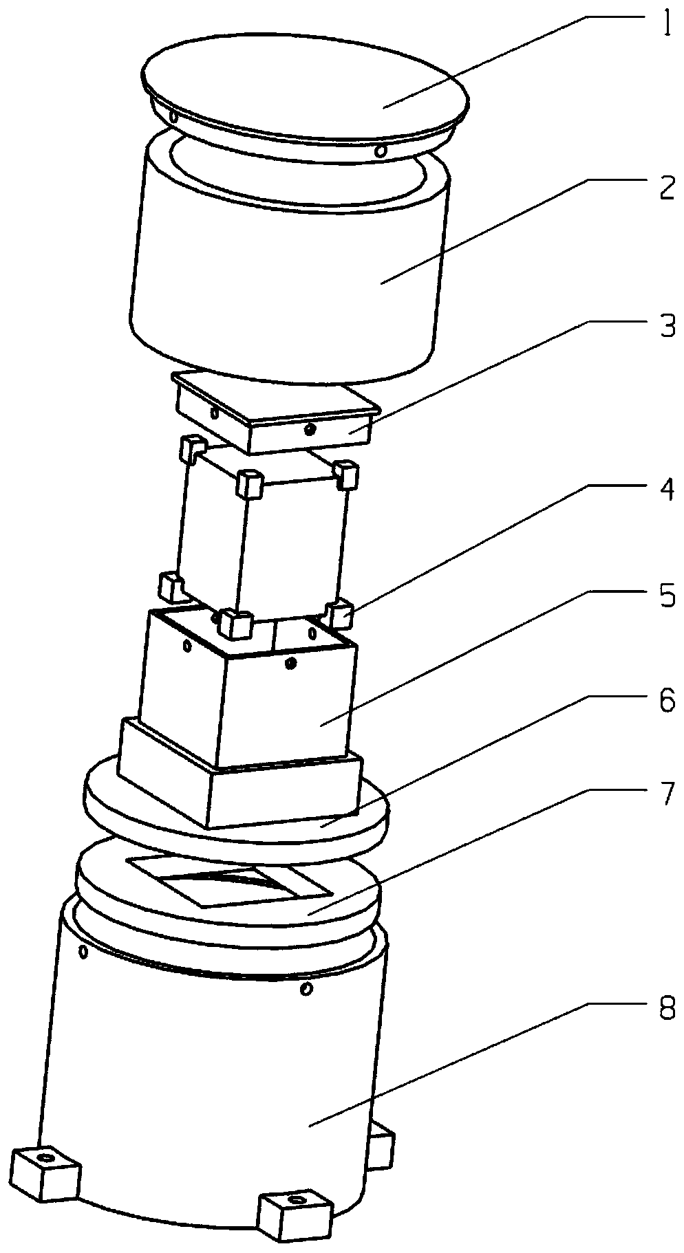
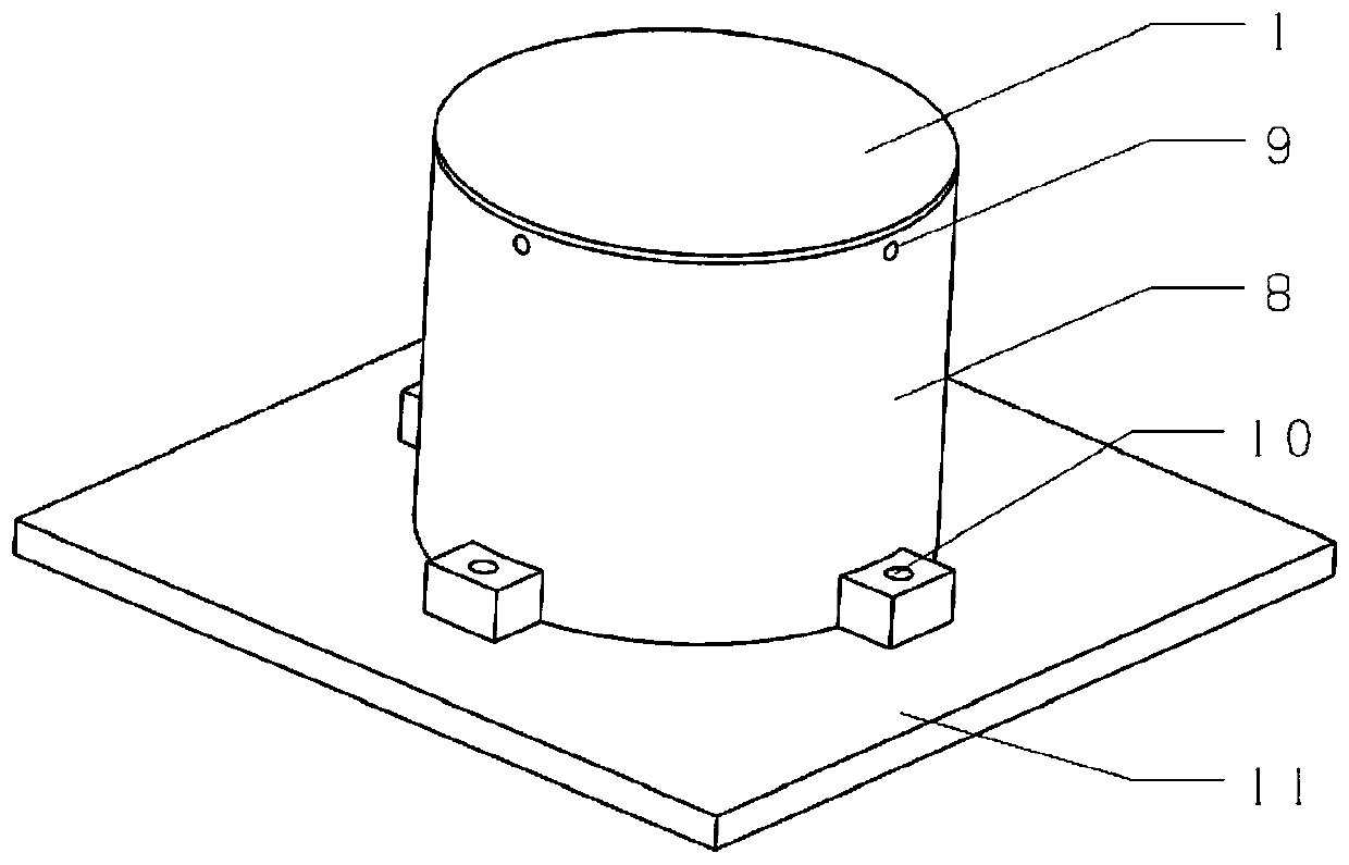
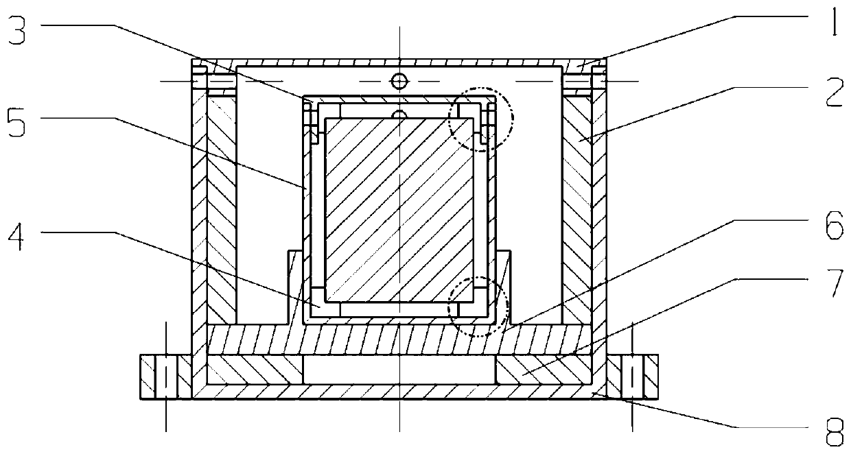
[0020] combine figure 1 , figure 2 , image 3 , the anti-high overload vibration damping structure for the reuse of the micro inertial measurement unit according to the present invention includes an outer shell, a support frame assembly, an inner shell, a buffer washer 7 and several vibration damping units. The outer shell is a closed structure, which is formed by connecting the first top cover 1 and the first base 8 by screws, and is placed on the working platform to accommodate the inner shell, buffer gasket 7 and several support frame components. The inner shell is arranged on Inside the outer shell, and a first cavity is formed between the inner shell and the outer shell; the support frame assembly is arranged in the first cavity for fixing and placing the inner shell, including the first assembly 2 and the second assembly 6, the second assembly The f...


PUM


Abstract

The invention discloses an anti-high-overload vibration reduction structure for reutilization of a micro-inertial measurement unit. The structure comprises an outer shell, an inner shell, a buffer washer, a support frame assembly and a plurality of vibration reduction units, and is characterized in that the outer shell is placed on a working platform, the inner shell is arranged in the outer shell, a first cavity is formed between the outer shell and the inner shell, the buffer washer is arranged at the bottom of the first cavity for buffering, the support frame assembly is arranged in the first cavity, located on the top face of the buffer washer and used for fixing and placing the inner shell, and the plurality of vibration reduction units are arranged in the inner shell, distributed inthe circumferential direction of the top face and the circumferential direction of the bottom face of the micro-inertial measurement unit to be measured correspondingly and attached to the inner shell. According to the structure, the first cavity between the outer shell and the inner shell is encapsulated by a pouring sealant, so that the high overload resistance of the micro-inertial measurementunit is improved.

Description

technical field [0001] The invention belongs to the technical field of vibration reduction, and in particular relates to an anti-high overload vibration reduction structure for repeated use of micro inertial measurement units. Background technique [0002] A micro-inertial measurement unit based on a micro-electromechanical system (Micro Electro Mechanical System, MEMS) is composed of three mutually orthogonal accelerometers, gyroscopes and other modules. The carrier position information can be obtained after processing the data obtained by the gyroscope and the accelerometer. Due to the advantages of small size and light weight, the micro inertial measurement unit has great application and development prospects in weapon shell guidance, vehicle guidance, unmanned aerial vehicle guidance, integrated navigation system and small reconnaissance equipment. However, vibrations often occur in the working environment of the MIMU, and these vibrations will degrade the performance o...

Claims


Application Information

Patent Timeline
Patent Type & Authority Applications(China)
IPC IPC(8): F16F15/08F16F15/02G01C21/16
CPCF16F15/085F16F15/02G01C21/16
Inventor 杨海波张弛尹晓春王昊宇赵子亮张伟廖文和
Owner NANJING UNIV OF SCI & TECH
Why Eureka
Try Eureka