Burner ring, burner and gas appliance
A burner and fire cover technology, applied in the direction of burner, gas fuel burner, combustion method, etc., can solve the problems of tempering, burner load is difficult to increase, etc., achieve infrared combustion stability, improve the mixed gas flow field, The effect of reducing the risk of flashback
Pending Publication Date: 2020-07-31
FOSHAN SHUNDE MIDEA WASHING APPLIANCES MFG
11 Cites 0 Cited by
AI-Extracted Technical Summary
Problems solved by technology
In the infrared burner in the related art, the gas directly enters the infrared combustion carrier for combust...
Method used
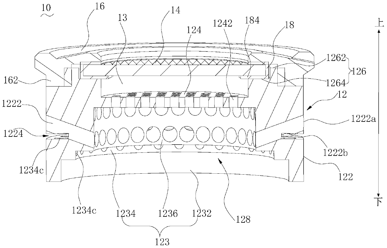
2 and 3, the annular peripheral wall 122 is provided with a flame-stabilizing groove 1224, the flame-stabilizing groove 1224 is located below the fire hole 1222, and the flame-stabilizing groove 1224 communicates with the fire hole 1222 and the mixing chamber 128. In this way, when the burner 100 is working, the flame formed by the flame stabilizing groove 1224 will stabilize the root of the flame formed by the fire hole 1222, which can prevent the gas from leaving the flame and deflaming in the fire hole 1222 or reduce the gas flow in the fire hole 1222. 1222 Probability of flame-out and fire-off. It can be understood that the flame stabilizing groove 1224 is annular and formed by the inward depression of the annular peripheral wall 122 .
In the embodiment of the present invention, fire cover body 12 integral body can adopt the material of aluminum or copper to be made into integral structure, and aluminum has the performance of good thermal processing and low cost, and copper has high temperature resistance characteristic, can guarantee internal fire The service life of cover 10. The annular cover 16 can also be made of aluminum or copper. The fire cover body 12 and the annular cover body 16 can be processed by casting and hot forging. In this way, the simple manufacturing method can effectively reduce the production cost of the fire cover 10 and improve a certain production efficiency.
In the gas appliance of the embodiment of the present invention, the fire cover 10 is provided with a buffer chamber 13 between the top wall 124 and the infrared combustion carrier 14, so that the mixed gas forms a reflow zone in the buffer chamber 13, which can reduce the risk of tempering , improve the flow field of the mixed gas, make the infrared combustion more stable, and can increase the load of the fire cover 10 .
It can be understood that the annular peripheral wall 122 is provided with a plurality of fire holes 1222, and a plurality of fire holes 1222 are distributed into two rows up and down along the circumferential direction of the annular peripheral wall 122, and the top wall 124 is provided with a plurality of through holes 1242 so that the top wall 124 forms mesh structure. The infrared combustion carrier 14 is a network structure with pores. A part of the gas mixture in the gas-mixing chamber 128 is sprayed outward through the fire hole 1222 of the annular peripheral wall 122, and is ignited for atmospheric combustion. A part passes through the through hole 1242 of the top wall 124 and sprays out from the infrared combustion carrier 14 arranged above the top wall 124 , and burns by infrared after being ignited. In the infrared combustion mode, the combustion of the mixed gas is more complete, the emission of smoke is low, and the noise is small. The fire cover 10 adopts a pseudo double-ring combustion structure of atmospheric combustion (atmospheric partial premixed combustion) and infrared combustion, realizing the coexistence of two combustion modes of mixed gas in the same channel, which can increase the load of the fire cover 10 and reduce the return air risk. The center of the fire cover 10 has heat radiation heat exchange, and side heat convection heat exchange.
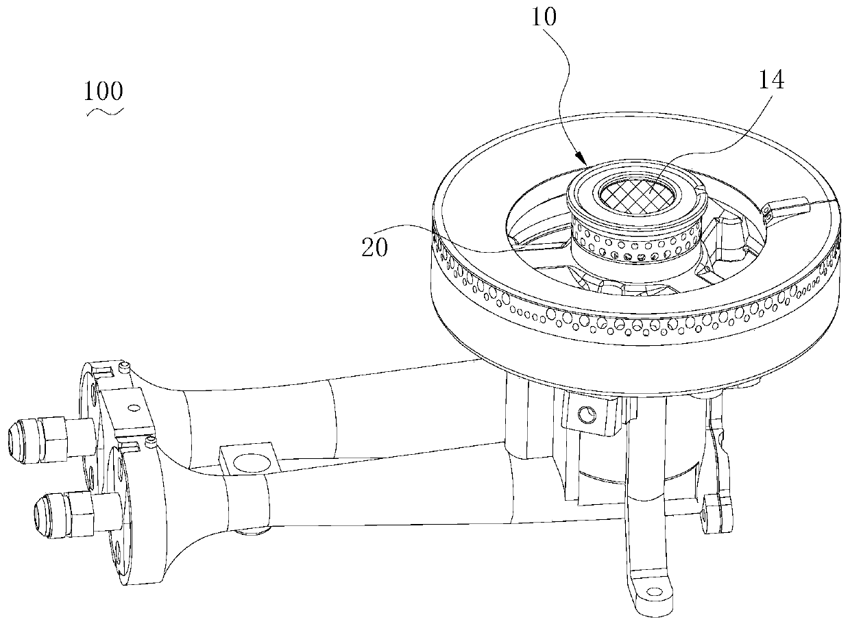
Please refer to Fig. 1 and Fig. 6, fire cover 10 can be used as the inner fire cover of burner 100, and the gas distribution plate 20 of burner 100 comprises inner ring cavity 22, and inner ring cavity 22 is provided with second ladder The collar 222 that fits the structure 123 . When installing the fire cover 10 to the gas distribution plate 20 of the burner 100 , the second stepped structure 123 can be connected with the flange 222 of the inner ring cavity 22 to facilitate the positioning and installation of the fire cover 10 . Specifically, the third step 1232 surrounds the convex edge 222 of the inner annular cavity 22 , and the convex edge 222 contacts the inner annular surface 1232 a of the third step 1232 and the step surface 1234 b of the fourth step 1234 .
Please refer to Fig. 3 and Fig. 4, the first stepped structure 126 protrudes on the top wall 124, the annular cover 16 is located on the first stepped structure 126, the top wall 124, the first stepped structure 126 and the annular cover 16 together form the receiving cavity 11 . The infrared combustion carrier 14 is located in the accommodating chamber and exposed from the middle of the annular cover 16 . In this way, the infrared combustion carrier 14 is pressed tightly in the accommodating cavity by the annular cover 16, the infrared combustion carrier 14 is not easy to fall off from the fire cover 10, and the upper and lower split ring cover 16 and the fire cover body 12 are easy to install and disassemble, which is convenient Replace the infrared combustion carrier 14. At the same time, the infrared combustion carrier 14 is arranged above the top wall 124 , and the mixed gas in the mixed gas chamber 128 can conduct infrared combustion on the infrared combustion carrier 14 through the through hole 1242 of the top wall 124 to form a central flame.
The burner 100 of the embodiment of the present invention, fire cap 10 is by setting buffer chamber 13 between top wall 124 and infrared combustion carrier 14, makes mixed gas form backflow zone in buffer chamber 13, can reduce tempering risk, improve the mixed gas flow velocity field, make the infrared combustion more stable, and can increase the load of the fire cover 10.
The fire cover 10 of the embodiment of the present invention, by setting buffer chamber 13 between top wall 124 and infrared combustion carrier 14, makes mixed gas form reflow zone in buffer chamber 13, can reduce tempering risk, improve...
Abstract
The invention discloses a burner ring, a burner and a gas appliance. The burner ring is used for the burner. The burner ring comprises a burner ring body and an infrared combustion carrier; the burnerring body comprises an annular peripheral wall and a top wall connected with the annular peripheral wall, and the infrared combustion carrier is arranged above the top wall; the annular peripheral wall and the top wall jointly form a gas mixing chamber, and the top wall is provided with through holes communicating with the gas mixing chamber and the infrared combustion carrier; a buffer chamber is formed between the top wall and the infrared combustion carrier, and the buffer chamber is in communication with the through holes; the gas mixing chamber is used for containing mixed gas of gas andair; and the burner ring is configured to allow the mixed gas to enter the buffer chamber from the gas mixing chamber through the through holes to form a reflux region in the buffer chamber. According to the burner ring, the buffer chamber is arranged between the top wall and the infrared combustion carrier, and the mixed gas forms the reflux area in the buffer chamber so that the backfire risk can be reduced, the flow velocity field of the mixed gas is improved, infrared combustion is stabler, and the load on the burner ring can be increased.
Application Domain
Domestic stoves or rangesGaseous fuel burner +1
Technology Topic
PhysicsChemistry +7
Image
Examples
- Experimental program(1)
Example Embodiment
[0027] The following describes the embodiments of the present invention in detail. Examples of the embodiments are shown in the accompanying drawings, wherein the same or similar reference numerals indicate the same or similar elements or elements with the same or similar functions. The following embodiments described with reference to the accompanying drawings are exemplary, and are only used to explain the present invention, but should not be understood as limiting the present invention.
[0028] In the description of the present invention, it should be understood that the terms "center", "longitudinal", "transverse", "length", "width", "thickness", "upper", "lower", "front", " "Back", "Left", "Right", "Vertical", "Horizontal", "Top", "Bottom", "Inner", "Outer", "Clockwise", "Counterclockwise" and other directions or The positional relationship is based on the position or positional relationship shown in the drawings, and is only for the convenience of describing the present invention and simplifying the description, and does not indicate or imply that the pointed device or element must have a specific orientation, be constructed and operated in a specific orientation, Therefore, it cannot be understood as a limitation to the present invention. In addition, the terms "first" and "second" are only used for descriptive purposes, and cannot be understood as indicating or implying relative importance or implicitly indicating the number of indicated technical features. Therefore, the features defined with "first" and "second" may explicitly or implicitly include one or more of the features. In the description of the present invention, "plurality" means two or more than two, unless specifically defined otherwise.
[0029] In the description of the present invention, it should be noted that the terms "installation", "connected" and "connected" should be understood in a broad sense, unless otherwise clearly specified and limited. For example, they can be fixed or detachable. Connect, or connect in one piece. It can be a mechanical connection or an electrical connection. It can be directly connected, or indirectly connected through an intermediate medium, and it can be a communication between two elements or an interaction relationship between two elements. For those of ordinary skill in the art, the specific meanings of the above terms in the present invention can be understood according to specific circumstances.
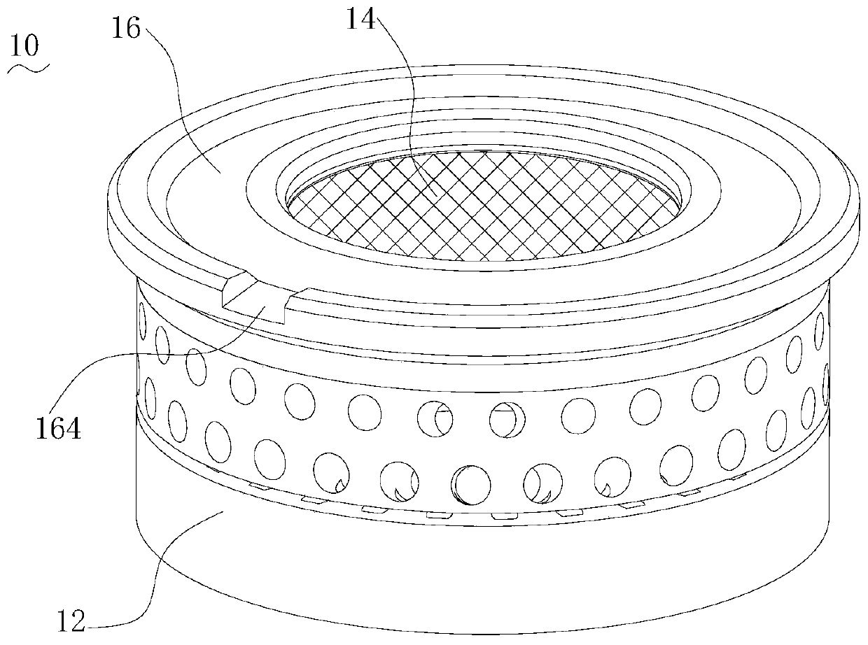
[0030] See Figure 1-Figure 5 , The fire cover 10 of the embodiment of the present invention is used for the burner 100. The fire cover 10 includes a fire cover body 12, an infrared combustion carrier 14 and an annular cover body 16. The fire cover body 12 includes an annular peripheral wall 122, a top wall 124 connected to the annular peripheral wall 122, and a first step structure 126 connected to the top wall 124. The annular peripheral wall 122 and the top wall 124 together form an air mixing chamber 128, and the air mixing chamber 128 is used to contain a mixed gas of fuel gas and air. The infrared combustion carrier 14 is arranged above the top wall 124. The annular peripheral wall 122 is provided with a fire hole 1222 communicating with the air mixing chamber 128, and the top wall 124 is provided with a through hole 1242 communicating with the air mixing chamber 128 and the infrared combustion carrier 14.
[0031] In this way, two combustion modes of atmospheric combustion and infrared combustion are realized through the same air mixing chamber 128, which can not only effectively improve the problem of high smoke emission, but also increase the load of the flame cover 10 and reduce the risk of backfire.
[0032] It can be understood that the annular peripheral wall 122 is provided with a plurality of fire holes 1222, and the plurality of fire holes 1222 are distributed in two rows along the circumference of the annular peripheral wall 122, and the top wall 124 is provided with a plurality of through holes 1242 so that the top wall 124 forms a mesh structure . The infrared combustion carrier 14 has a network structure with pores. A part of the mixed gas in the mixing chamber 128 is injected outwards through the fire hole 1222 of the annular peripheral wall 122, and is ignited for atmospheric combustion. A part of the infrared combustion carrier 14 provided above the top wall 124 is ejected through the through hole 1242 of the top wall 124, and the infrared combustion carrier 14 is ignited to perform infrared combustion. In the infrared combustion mode, the combustion of the mixed gas is more complete, the exhaust gas is low, and the noise is low. The fire cover 10 adopts the pseudo double-ring combustion structure of atmospheric combustion (atmospheric partial premixed combustion) and infrared combustion, which realizes the coexistence of two combustion methods of mixed gas in the same channel, which can increase the load of the fire cover 10 and reduce the return air risk. The heat radiation heat exchange at the center of the fire cover 10, and the heat convection heat exchange at the side.
[0033] In the embodiment of the present invention, the fire cover body 12 as a whole can be made of aluminum or copper into an integrated structure. Aluminum has good thermal processing performance and low cost, while copper has high temperature resistance characteristics, which can ensure the internal fire cover 10 Service life. The annular cover 16 can also be made of aluminum or copper. The fire cover body 12 and the annular cover body 16 can be processed by casting and hot forging manufacturing methods. In this way, a simple manufacturing method can effectively reduce the production cost of the fire cover 10 and improve a certain production efficiency.
[0034] In the embodiment of the present invention, the infrared combustion carrier 14 includes at least one of metal fiber mesh, iron chromium aluminum mesh plate and carbon silicon fiber mesh. It is understandable that the infrared combustion carrier 14 can be a metal fiber mesh, a iron chromium aluminum mesh plate or a carbon silicon fiber mesh, or a combination of metal fiber mesh, iron chromium aluminum mesh plate and carbon silicon fiber mesh, or a metal fiber mesh, Three combinations of iron-chromium-aluminum mesh and carbon-silicon fiber mesh. Weaving can be used to form metal fiber mesh and carbon silicon fiber mesh. As the infrared combustion carrier 14, the metal fiber mesh has high heat radiation efficiency, is not easy to temper and has a long service life. The iron-chromium-aluminum mesh plate has high temperature resistance, reliable structure, easy to burn, low cost, and can use the flame to burn the outer flame to burn the iron-chromium-aluminum mesh plate; due to the large porosity of the iron-chromium-aluminum mesh plate, it can be used Multiple layers of screens with different meshes are superimposed to prevent tempering. The carbon silicon fiber mesh has large porosity and uniform structure, and the thermal load range for infrared combustion is relatively wide.
[0035] In the illustrated embodiment, the fire cover 10 has a substantially cylindrical shape as a whole. In other embodiments, the fire cover 10 as a whole may be in the shape of a truncated cone, a cube, or the like. Hereinafter, the fire cover 10 is basically cylindrical in shape as a whole for detailed description.
[0036] See image 3 with Figure 4 The first stepped structure 126 is protrudingly provided on the top wall 124, the annular cover 16 is provided on the first stepped structure 126, and the top wall 124, the first stepped structure 126 and the annular cover 16 jointly form the accommodating cavity 11. The infrared combustion carrier 14 is located in the containing cavity and exposed from the middle of the annular cover 16. In this way, the infrared combustion carrier 14 is pressed into the accommodating cavity by the annular cover 16, the infrared combustion carrier 14 is not easy to fall off from the fire cover 10, and the upper and lower split annular cover 16 and the fire cover body 12 are easy to install and disassemble, which is convenient Replace the infrared combustion carrier 14. At the same time, the infrared combustion carrier 14 is arranged above the top wall 124, and the mixed gas in the air mixing chamber 128 can pass through the through holes 1242 of the top wall 124 to perform infrared combustion on the infrared combustion carrier 14 to form a central flame.
[0037] Specifically, the first step structure 126 includes a first step 1262 and a second step 1264 that are connected. The second step 1264 and the first step 1262 are sequentially distributed outwards along the central axis X of the fire cover 10, and the annular cover 16 is provided with a convex The edge 162 and the convex edge 162 are matched with the first step 1262, and the infrared combustion carrier 14 is arranged on the second step 1264.
[0038] It can be understood that both the first step 1262 and the second step 1264 are in a circular ring shape, and the central axis of the first step 1262 and the second step 1264 coincides with the central axis X of the fire cover 10 (the coincidence may include complete coincidence, or both The deviation is within the desired range), the distance from the inner ring surface 1262a of the first step 1262 to the central axis X of the fire cover 10 is greater than the distance from the inner ring surface 1264a of the second step 1264 to the central axis X of the fire cover 10, The step 1262 is located above the second step 1264. The infrared combustion carrier 14 is disposed on the second step 1264, and the infrared combustion carrier 14 is in contact with the step surface 1264b of the second step 1264 and in contact with the inner ring surface 1262a of the first step 1262. The convex edge 162 of the annular cover 16 also has a circular ring shape, and the convex edge 162 is matched with the first step 1262. Therefore, after the infrared combustion carrier 14 is disposed on the second step 1264, the annular cover 16 is disposed on the first step structure 126, the convex edge 162 is matched with the first step 1262, and the first step 1262 is located inside the convex edge 162, Thus, the infrared combustion carrier 14 provided on the second step 1264 is confined in the containing cavity and compressed.
[0039] In other embodiments, the first stepped structure 126 may include an annular step, and the infrared combustion carrier 14 may be arranged on the step surface of the annular step; or the infrared combustion carrier 14 may be directly arranged on the top wall 124, and infrared combustion The peripheral side surface of the carrier 14 is in contact with the inner ring surface of the annular step.
[0040] Further, the fire cover 10 includes an annular fastener 18, which connects the first step structure 126 and fixes the infrared combustion carrier 14 to the first step structure 126. It can be understood that the fire cover 10 is an upper and lower split type, and includes a fire cover body 12, a ring cover body 16, an infrared combustion carrier 14, and a ring fastener 18. The ring fastener 18 includes a ring 182 and a crimping edge 184 protruding inward from the outer periphery of the ring 182. Specifically, the ring 182 has a circular ring shape, and the infrared combustion carrier 14 has a circular shape. The infrared combustion carrier 14 is accommodated in the space formed between the ring 182 and the blank holder 184 and is fastened by the ring 182 and the blank holder 184. On the one hand, the periphery of the infrared combustion carrier 14 is covered by the ring fastener 18 to protect the infrared combustion carrier 14; on the other hand, when the infrared combustion carrier 14 uses metal fiber mesh, iron chromium aluminum mesh and carbon silicon fiber When one or more of the nets are superimposed, the ring-shaped fastener 18 can fasten the multilayer material of the infrared combustion carrier 14. The ring fastener 18 can be made of high temperature resistant metal material.
[0041] When assembling the fire cover 10, the infrared combustion carrier 14 and the ring fastener 18 can be assembled as a whole. For example, the infrared combustion carrier 14 has a certain amount of deformation, and the infrared combustion carrier 14 can be pressed into the ring through its own deformation. In the space formed between 182 and the blank holder 184, the infrared combustion carrier 14 is clamped by the ring fastener 18, and then the ring fastener 18 with the infrared combustion carrier 14 is placed on the second step 1264, and passes through the ring cover The body 16 cooperates with the first step structure 126 to press the ring fastener 18 with the infrared combustion carrier 14 to form the fire cover 10. After the assembly is completed, the ring fastener 18 with the infrared combustion carrier 14 is in contact with the step surface 1264b of the second step 1264 and the inner ring surface 1262a of the first step 1262.
[0042] In the embodiment of the present invention, the ring-shaped cover 16 and the first stepped structure 126 can be connected by screwing. Specifically, the first step 1262 of the first stepped structure 126 is provided with an external thread, and the inner side of the convex edge 162 of the annular cover 16 is provided with an internal thread that cooperates with the external thread. The protruding edge 162 is connected with the first step 1262 through a screw thread, so that the annular cover 16 is arranged on the first step structure 126 and presses the infrared combustion carrier 14. The ring-shaped cover 16 and the first stepped structure 126 are connected more reliably by threaded fitting, and are convenient for installation and disassembly. At the same time, through the combination of multiple parts, the coexistence of two combustion modes in the same channel can be realized. In other embodiments, the annular cover 16 and the first stepped structure 126 can be fixed by screw connection, riveting or other connection methods.
[0043] See figure 2 , The upper surface of the annular cover 16 is provided with a diversion groove 164. It can be understood that during the cooking process of the user, the liquid may drip onto the fire cover 10. The arrangement of the diversion groove 164 can divert the accumulation of liquid on the annular cover 16 and play an anti-blocking effect. In the illustrated embodiment, the upper surface of the annular cover 16 is provided with a convex ring, and the peripheral wall of the convex ring is provided with a diversion groove 164. In other embodiments, the peripheral wall of the convex ring may be provided with two or more diversion grooves 164, and the two or more diversion grooves 164 are evenly spaced. It can be understood that, in other embodiments, the upper surface of the annular cover 16 is flat as a whole, and the diversion groove 164 may be formed by recessing the upper surface of the annular cover 16 downward.
[0044] See figure 2 with image 3 , The annular peripheral wall 122 is provided with a flame-stabilizing groove 1224, which is located below the fire hole 1222, and the flame-stabilizing groove 1224 communicates with the fire hole 1222 and the air mixing chamber 128. In this way, when the burner 100 is working, the flame formed by the flame stabilizing groove 1224 will stabilize the flame root formed by the flame hole 1222, which can prevent the gas from leaving the flame and the flame out of the flame hole 1222 or reduce the gas in the flame hole. 1222 The probability of flame separation and flame loss. It can be understood that the flame stabilizing groove 1224 has a ring shape and is formed by the annular peripheral wall 122 recessed inward.
[0045] Further, the fire hole 1222 includes a first injection port 1222a and a second injection port 1222b, and the second injection port 1222b communicates with the flame stabilizing groove 1224. The mixed gas is injected from the fire hole 1222 to the first injection port 1222a and the second injection port 1222b, and the mixed gas is ignited and burned to form a flame. The second injection port 1222b is connected to the flame stabilizing groove 1224, and can supplement the flame stabilizing groove 1224 with mixed gas, so that the flame formed in the flame stabilizing groove 1224 is more stable. In the illustrated embodiment, the fire hole 1222 is inclined outward with respect to the central axis X of the fire cover 10. In this way, the length of the fire hole 1222 is increased, so that more mixed gas is stored in the fire hole 1222, so that the flame at the fire hole 1222 burns stably. In the present invention, the central axis X of the fire cover 10 is along the vertical direction, and the inclination does not include the horizontal direction, which means that the central axis of the fire hole 1222 intersects the central axis X of the fire cover 10 and is not perpendicular. The inclination angle of the fire hole 1222 with respect to the central axis X of the fire cover 10 may be 20 degrees to 45 degrees, for example, the inclination angle is 20 degrees, 45 degrees, or other degrees between 20 degrees and 45 degrees.
[0046] See Figure 5 , The lower end of the annular peripheral wall 122 forms a second stepped structure 123. It can be understood that the arrangement of the second stepped structure 123 facilitates the positioning and installation of the fire cover 10 to the burner 100. Specifically, the second stepped structure 123 includes a connected third step 1232, a fourth step 1234, and a fifth step 1236. The fifth step 1236, the fourth step 1234, and the third step 1232 extend outward along the central axis X of the fire cover 10. Distributed sequentially. The third step 1232, the fourth step 1234, and the fifth step 1236 are in a circular ring shape. The central axis of the third step 1232, the fourth step 1234 and the fifth step 1236 coincide with the central axis X of the fire cover 10 (the overlap may include The distance from the inner ring surface 1232a of the third step 1232 to the central axis X of the fire cover 10 is greater than the distance from the inner ring surface 1234a of the fourth step 1234 to the fire cover 10 The distance from the central axis X of the inner ring surface 1234a of the fourth step 1234 to the central axis X of the fire cover 10 is greater than the distance from the inner ring surface 1236a of the fifth step 1236 to the central axis X of the fire cover 10.
[0047] See figure 1 with Image 6 The fire cover 10 can be used as the inner fire cover of the combustor 100. The gas distribution plate 20 of the combustor 100 includes an inner ring cavity 22, and the inner ring cavity 22 is provided with a convex edge 222 matched with the second step structure 123. When installing the fire cover 10 to the gas distribution plate 20 of the combustor 100, the second step structure 123 can be matedly connected with the convex edge 222 of the inner ring cavity 22 to facilitate the positioning and installation of the fire cover 10. Specifically, the third step 1232 surrounds the convex edge 222 of the inner ring cavity 22, and the convex edge 222 contacts the inner ring surface 1232 a of the third step 1232 and the step surface 1234 b of the fourth step 1234.
[0048] Further, the fourth step 1234 is provided with a flame stabilizing hole 1234c, the flame stabilizing hole 1234c is connected to the mixing chamber 128 and the flame stabilizing groove 1224, and the fifth step 1236 is provided with a fire hole 1222. It can be understood that the outer ring surfaces of the fourth step 1234 and the fifth step 1236 extend and overlap, and the thickness of the fourth step 1234 is smaller than the thickness of the fifth step 1236. Since the flame stabilizing hole 1234c is opened on the fourth step 1234 and the fire hole 1222 is opened on the fifth step 1236, the space of the air mixing chamber 128 corresponding to the flame stabilizing hole 1234c is relatively large. Compared with the embodiment in which the flame stabilizing hole 1234c and the fire hole 1222 are opened on the annular peripheral wall 122 of the same thickness, in this embodiment, the flame stabilizing hole 1234c is opened in the fourth step 1234, so that the flame stabilizing hole 1234c has more air intake. Good flame stabilization effect.
[0049] See image 3 A buffer chamber 13 is formed between the top wall 124 and the infrared combustion carrier 14, and the buffer chamber 13 communicates with a through hole 1242. The mixed gas chamber 128 is used to contain a mixed gas of fuel gas and air. The fire cover 10 is configured to allow the mixed gas to enter the buffer chamber 13 from the gas mixing chamber 128 through the through hole 1242 and form a reflux area in the buffer chamber 13. The arrangement of the buffer chamber 13 enables the mixed gas to form a return zone in the buffer chamber 13, further reduces the risk of backfire, improves the flow field of the mixed gas, makes infrared combustion more stable, and can increase the load of the fire cover 10.
[0050] It can be understood that, compared to a fire cover with a single gas mixing chamber, the fire cover 10 of the present invention includes two communicating chambers, a gas mixing chamber 128 and a buffer chamber 13, due to the volume of the through hole 1242 for the mixed gas to pass through. The volume of the mixed gas is smaller than the volume of the mixed gas contained in the buffer chamber 13. When the mixed gas enters the buffer chamber 13 from the gas mixing chamber 128 through the through hole 1242 of the top wall 124, the volume of the mixed gas suddenly expands, forming a backflow in the buffer chamber 13 Zone, the gas and air mixture is mixed more evenly by the gas disturbance in the recirculation zone, the gas and air reach a completely premixed state, and burn rapidly in the pore channels of the infrared combustion carrier 14, making the surface appear red ; At the same time, the buffer chamber 13 can also be pressurized and decelerated to slow down the flow rate of the mixed gas, so that the mixed gas escapes from the infrared combustion carrier 14 for combustion at a very small speed (usually 0.1 to 0.14 m/s). Due to the combustion of the mixed gas, the temperature of the reflux zone formed by the mixed gas in the buffer chamber 13 is relatively high. The high-temperature reflux zone can heat the mixed gas during combustion and at the same time act as a stable ignition source to make it enter the buffer chamber 13 The mixed gas immediately burns, ensuring a higher combustion heat intensity and combustion temperature. Under this combustion structure, the propagation speed of the mixed gas can be slowed down, the flow rate field of the mixed gas is more uniform, the residence time of infrared combustion is increased, the combustion is more complete and stable, and backfire is prevented.
[0051] In one embodiment, part of the mixed gas in the same mixing chamber 128 of the fire cover 10 passes through the fire hole 1222 of the annular peripheral wall 122 for direct atmospheric partial premixed combustion, and part passes through the through hole 1242 of the top wall 124 in the buffer chamber. After the chamber 13 is further mixed, infrared combustion is performed on the infrared combustion carrier 14. The fire cover 10 includes two chambers, a gas mixing chamber 128 and a buffer chamber 13, so that the gas and air in the fire cover 10 have two mixing states, which better realizes the coexistence of atmospheric combustion and infrared combustion.
[0052] In the illustrated embodiment, the first step structure 126 includes a first step 1262 and a second step 1264 protruding on the top wall 124. The infrared combustion carrier 14 is provided on the second step 1264. Height, a buffer chamber 13 is formed between the top wall 124 and the infrared carrier. In other embodiments, the first step structure 126 may include an annular step protruding from the top wall 124, and the infrared combustion carrier 14 may be provided on the annular step. Due to the height of the annular step, the top wall A buffer chamber 13 is formed between 124 and the infrared carrier.
[0053] In summary, the fire cover 10 of the embodiment of the present invention includes a fire cover body 12 and an infrared combustion carrier 14. The fire cover body 12 includes an annular peripheral wall 122 and a top wall 124 connected to the annular peripheral wall 122. The infrared combustion carrier 14 is disposed above the top wall 124. The annular peripheral wall 122 and the top wall 124 together form an air mixing chamber 128, and the top wall 124 is provided with a through hole 1242 connecting the air mixing chamber 128 and the infrared combustion carrier 14. A buffer chamber 13 is formed between the top wall 124 and the infrared combustion carrier 14, and the buffer chamber 12 communicates with a through hole 1242. The mixed gas chamber 128 is used to contain a mixed gas of fuel gas and air. The fire cover 10 is configured to allow the mixed gas to enter the buffer chamber 13 from the gas mixing chamber 128 through the through hole 1242 and form a reflux area in the buffer chamber 13.
[0054] In the fire cover 10 of the embodiment of the present invention, by providing a buffer chamber 13 between the top wall 124 and the infrared combustion carrier 14, the mixed gas forms a return zone in the buffer chamber 13, which can reduce the risk of backfire and improve the flow rate of the mixed gas Field, the infrared combustion is more stable, and the load of the fire cover 10 can be increased.
[0055] See figure 1 with Image 6 The burner 100 of the embodiment of the present invention includes the fire cover 10 of the above-mentioned embodiment.
[0056] In the burner 100 of the embodiment of the present invention, the flame cover 10 is provided with a buffer chamber 13 between the top wall 124 and the infrared combustion carrier 14, so that the mixed gas forms a recirculation zone in the buffer chamber 13, which can reduce the risk of backfire and improve The mixed gas velocity field makes the infrared combustion more stable and can increase the load of the fire cover 10.
[0057] When the fire cover 10 is in use, it can be used as an inner fire cover to be set on the inner ring cavity 22 of the gas distribution plate 20 of the burner 100 and used in conjunction with the gas distribution plate 20. The combustible mixed gas of fuel gas and air in the gas mixing chamber 128 can be provided by an inner ring fuel gas passage of the gas distributor 20. The burner 100 can be applied to gas appliances such as gas stoves, ovens, and gas water heaters.
[0058] The gas appliance of the embodiment of the present invention includes the burner 100 of the above-mentioned embodiment.
[0059] In the gas appliance of the embodiment of the present invention, the flame cover 10 is provided with a buffer chamber 13 between the top wall 124 and the infrared combustion carrier 14, so that the mixed gas forms a return zone in the buffer chamber 13, which can reduce the risk of backfire and improve the mixing The gas velocity field makes infrared combustion more stable and can increase the load of the fire cover 10.
[0060] Specifically, in the case that the gas appliance is a gas cooker, the gas cooker further includes a housing, a panel, and a control structure. The panel cover is arranged above the housing and is provided with mounting holes. The burner 100 is partially located in the housing and is installed by The hole is exposed, and the control structure is arranged on the panel and used for the user to control the gas cooker. In a specific embodiment, the control structure may include a knob structure. In this way, the control structure can be used to separately control the gas delivery to the inside of the combustor 100, and adjust the flow of gas through the control structure to control the firepower of the combustor 100. In this way, the gas stove can be applied to a variety of working environments, for example, the gas stove can be used for steaming, boiling, roasting, and frying in cooking.
[0061] In the present invention, unless expressly stipulated and defined otherwise, the "above" or "below" of the first feature of the second feature may include the first and second features in direct contact, or may include the first and second features Not in direct contact but through other features between them. Moreover, "above", "above" and "above" the second feature of the first feature include the first feature being directly above and obliquely above the second feature, or it simply means that the level of the first feature is higher than the second feature. The "below", "below", and "below" of the first feature of the second feature include the first feature directly below and obliquely below the second feature, or it simply means that the level of the first feature is smaller than the second feature.
[0062] The disclosure herein provides many different embodiments or examples for realizing different structures of the present invention. In order to simplify the disclosure of the present invention, the components and settings of specific examples are described herein. Of course, they are only examples, and are not intended to limit the invention. In addition, the present invention may repeat reference numerals and/or reference letters in different examples. Such repetition is for the purpose of simplification and clarity, and does not indicate the relationship between the various embodiments and/or settings discussed. In addition, the present invention provides examples of various specific processes and materials, but those of ordinary skill in the art may be aware of the application of other processes and/or the use of other materials.
[0063] In the description of this specification, the description with reference to the terms "one embodiment", "some embodiments", "exemplary embodiments", "examples", "specific examples", or "some examples" etc. means to combine the embodiments The specific features, structures, materials, or characteristics described by the examples are included in at least one embodiment or example of the present invention. In this specification, the schematic representation of the above-mentioned terms does not necessarily refer to the same embodiment or example. Moreover, the described specific features, structures, materials or characteristics can be combined in an appropriate manner in any one or more embodiments or examples.
[0064] Although the embodiments of the present invention have been shown and described, those of ordinary skill in the art can understand that various changes, modifications, substitutions, and modifications can be made to these embodiments without departing from the principle and purpose of the present invention. The scope of the present invention is defined by the claims and their equivalents.
PUM


Description & Claims & Application Information
We can also present the details of the Description, Claims and Application information to help users get a comprehensive understanding of the technical details of the patent, such as background art, summary of invention, brief description of drawings, description of embodiments, and other original content. On the other hand, users can also determine the specific scope of protection of the technology through the list of claims; as well as understand the changes in the life cycle of the technology with the presentation of the patent timeline. Login to view more.