
A kind of miniature non-premixed burner with corrugated plate

A corrugated plate and burner technology, applied in the field of micro-miniature non-premixed burners, can solve the problems of complicated internal structure and processing technology of the burner, limited flame stability of the micro-burner, uneven thermal stress, etc. Fire risk, enhanced flame stability, enhanced mixing effects

Active Publication Date: 2020-07-28
HUAZHONG UNIV OF SCI & TECH
View PDF5 Cites 0 Cited by
  • Summary
  • Abstract
  • Description
  • Claims
  • Application Information

AI Technical Summary

Problems solved by technology

However, the above method has the following deficiencies when aiming at the flat-plate micro-combustor used for the thermal photovoltaic system: (1) most of the prior art work adopts the premixed combustion mode, and there is backfire under the condition of low speed and high equivalence ratio Risk; (2) The existing technology achieves a uniformly distributed outer wall temperature by setting a single sudden expansion or concave cavity. However, this setting has limited improvement effects on the system, and setting multiple structures will make the internal structure of the burner and The processing technology becomes complicated, and at the same time, the device fails due to the uneven thermal stress between the components; (3) the prior art does not utilize the preheating of fuel combustion, and the flame stability in the micro burner is limited to a certain extent

Method used


Image

  • A kind of miniature non-premixed burner with corrugated plate
  • A kind of miniature non-premixed burner with corrugated plate
  • A kind of miniature non-premixed burner with corrugated plate

Examples


Embodiment

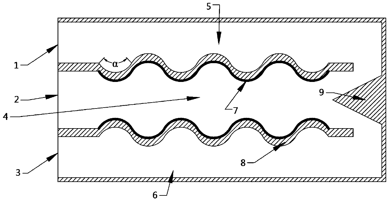
[0043] The specific parameters of the embodiment are as follows: the fuel is hydrogen, and the oxidant is air. The length, width and height of the burner are 40mm, 20mm and 5mm respectively. The number of corrugations is 4, the corrugation radian α is 60°, and the surface of the corrugated plate facing the combustion chamber is coated with catalyst. The cross-section of the turbulent body is an equilateral triangle with a side length of 6mm.

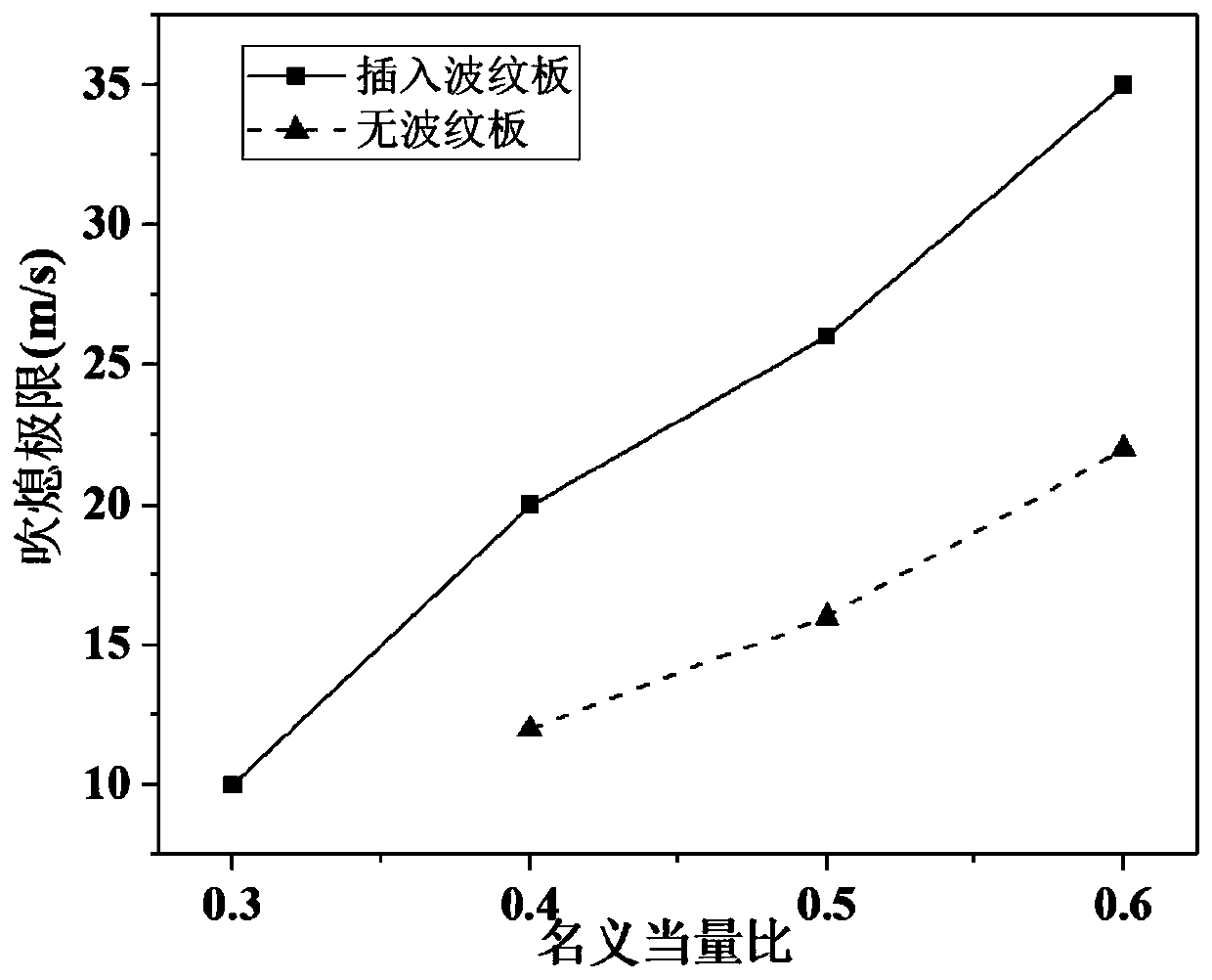
[0044] image 3 It is a comparison of the blow-out limit of the miniature non-premixed burner with corrugated plate and the miniature non-premixed burner with straight channel constructed according to the preferred embodiment of the present invention. From image 3 It can be seen that, when the nominal equivalence ratio is 0.4, 0.5, 0.6, adding the corrugated plate increases the blow-out limit of the burner, especially when the nominal equivalence ratio is 0.3, the straight channel burner without the corrugated plate is at all speeds ...


PUM


Abstract

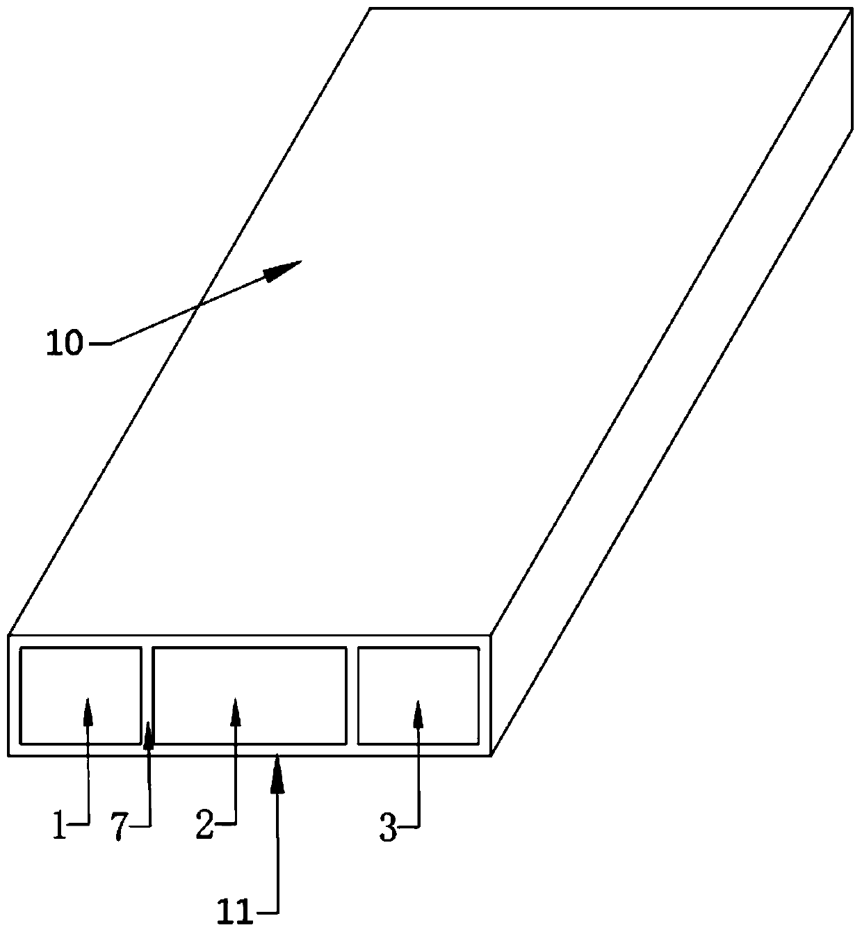
The invention belongs to the technical field of micro combustion, and discloses a micro non-premixing burner with a corrugated plate. The micro non-premixing burner with the corrugated plate comprisesa burner outer wall and a corrugated plate, wherein the burner outer wall comprises a rear side wall, an upper side wall and a lower side wall, the corrugated plate comprises a first corrugated plateand a second corrugated plate, the two side edges of the first corrugated plate and the two side edges of the second corrugated plate are fixedly connected with the upper side wall and the lower sidewall respectively, and distance communicating with a fuel preheating flow channel and a burning chamber is arranged between the first corrugated plate and the rear side wall, and the distance communicating with an air preheating flow channel and the burning chamber is formed between the first corrugated plate and the rear side wall; and a turbulent fluid is arranged on the rear side wall. According to the micro non-premixing burner, a mixing effect between fuel and air is enhanced, the flame stability in the micro burner is enhanced, the uniform outer wall temperature can be further obtained,the tempering risk is reduced, the micro non-premixing burner has the characteristics of being compact in structure, convenient to manufacture and use, wide in application range, so that is particularly suitable for a combustion energy supply occasion such as a micro-electro-mechanical system or a micro-aircraft.

Description

technical field [0001] The invention belongs to the technical field of micro-scale combustion, and more specifically relates to a miniature non-premixed burner with a corrugated plate. Background technique [0002] Micro-electro-mechanical systems include micro-sensors, micro-robots, handheld computers, and more. Traditional chemical batteries are bulky, heavy, and low in energy density, while the energy density of hydrogen and hydrocarbon fuels is hundreds of times that of traditional chemical batteries, and the sources are sufficient. Therefore, combustion-based micro energy power systems have received extensive attention. [0003] When the size of the burner is reduced, the / body ratio will increase sharply, resulting in a sharp increase in surface heat dissipation loss. On the one hand, it will make it difficult to maintain a stable flame in the burner. However, if the surface radiant energy is used to generate electricity through photovoltaic cells, or a thermoelectric...

Claims


Application Information

Patent Timeline
Patent Type & Authority Patents(China)
IPC IPC(8): F23D14/22F23D14/70F23D14/46F23D14/66
CPCY02E20/34
Inventor 范爱武袁自力李林洪
Owner HUAZHONG UNIV OF SCI & TECH
Learn More