Code reading and coding all-in-one machine

An all-in-one, code-reading camera technology, applied in the field of code-reading and coding-integrated machines, can solve the problems of low focusing efficiency, large volume, waste of man-hours and materials, etc., to improve assembly efficiency, ensure stable scanning, and facilitate installation.

Inactive Publication Date: 2020-08-04
WUXI BOLN LASER TECH
View PDF6 Cites 2 Cited by
  • Summary
  • Abstract
  • Description
  • Claims
  • Application Information

AI Technical Summary

Problems solved by technology

[0002] At present, when laser marking a product, the marking system needs to scan the marked product through the code reading device after the product is marked to confirm the marking effect. This code reading method cannot achieve code marking. , and scan the code at the same time, the system needs to move the product to the code scanning station through a special linear drive mechanism after the code is printed, which increases the product code reading time and reduces the efficiency of code scanning
At the same time, since the code reading and scanning equipment are separately set on the rack, the structure is not compact enough, the volume is large, and it is not convenient for storage, transportation and portability.
[0003] And when the product is replaced on the production line, the laser coding machine needs to refocus according to the new product. Since the laser is invisible light, the focus needs to be found through continuous trial and error; the focus efficiency is low, wasting man-hours and materials

Method used


Image

  • Code reading and coding all-in-one machine
  • Code reading and coding all-in-one machine
  • Code reading and coding all-in-one machine

Examples


Embodiment Construction

[0032] The technical solutions in the embodiments of the present invention will be clearly and completely described below with reference to the accompanying drawings in the embodiments of the present invention. Obviously, the described embodiments are only a part of the embodiments of the present invention, but not all of the embodiments. Based on the embodiments of the present invention, all other embodiments obtained by those of ordinary skill in the art without creative efforts shall fall within the protection scope of the present invention.

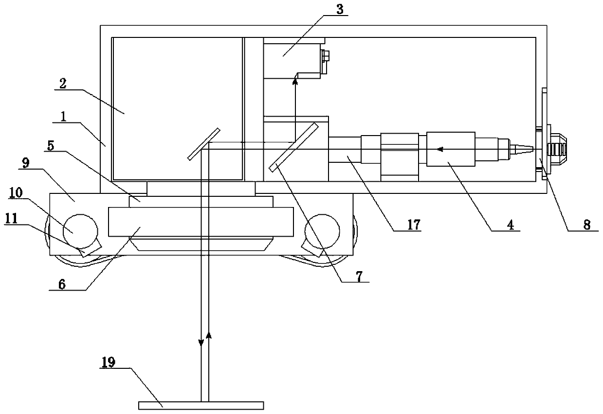
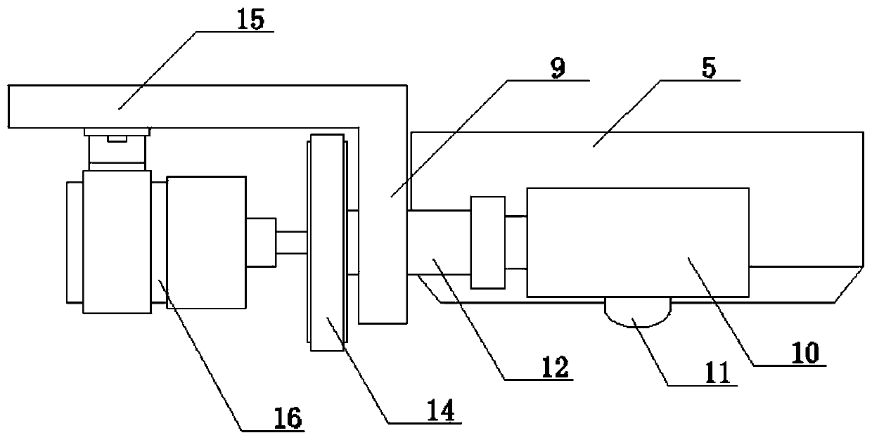
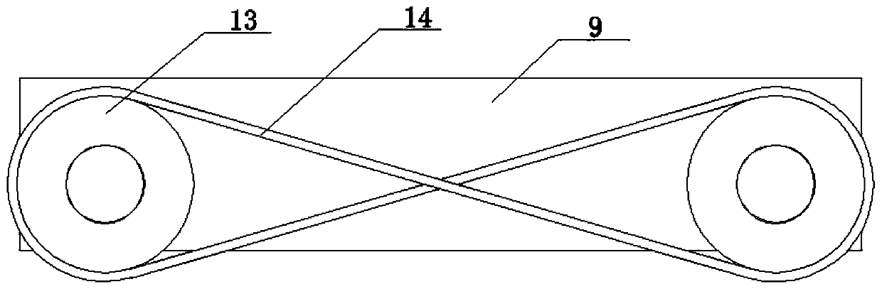
[0033] see Figures 1 to 9 , The present invention provides a technical solution: a code reading and coding integrated machine, comprising a casing 1, and the interior of the casing 1 is provided with a galvanometer scanning head 2, a code reading camera 3, a laser output isolator 4 and a semi-transparent and semi-transparent Mirror 7, the lower end of the housing 1 is provided with a field mirror 5, the field mirror 5 is connected wi...


PUM


Abstract

The invention relates to the technical field of laser marking machine, in particular to a code reading and coding all-in-one machine which comprises a shell. A galvanometer scanning head, a code reading camera, a laser output isolator and a half transparent and half reflecting mirror are arranged in the shell; a field lens is arranged at the lower end of the shell and is connected with the galvanometer scanning head; a visible light source and a visible light focusing assembly are connected to the lower end of the field lens; a laser input port is fixedly connected to one end of the shell; a laser light input from the laser input port is transmitted to the surface of a workpiece under the field lens by sequentially passing through the laser output isolator, the half transparent and half reflecting mirror and the galvanometer scanning head; and a visible light emitted by the visible light source is reflected through the workpiece and transmitted to the half transparent and half reflecting mirror through the field lens and the galvanometer scanning head, and is reflected to the code reading camera through the half transparent and half reflecting mirror. Through arranging the visiblelight focusing assembly, invisible laser focal points can be displayed through the visible light, and the position of a laser focal point can be quickly found through a visible light focal point whena production line product is replaced.

Description

technical field [0001] The invention relates to the technical field of laser marking machines, in particular to a code reading and coding integrated machine. Background technique [0002] At present, when laser marking a product, the marking system needs to scan the marked product through a code reading device after the product is marked to confirm the coding effect. This code reading method cannot realize coding. The system needs to move the product to the scanning station to scan the code through a special linear drive mechanism after the coding is completed, thereby increasing the product code reading time and reducing the efficiency of code scanning. At the same time, since the code reading and scanning equipment are separately arranged on the rack, the structure is not compact enough, the volume is large, and it is inconvenient to store, transport and carry. [0003] And when the product is replaced in the production line, the laser coding machine needs to refocus acco...

Claims


Application Information

Patent Timeline
Patent Type & Authority Applications(China)
IPC IPC(8): B23K26/046B23K26/064B23K26/082B23K26/362B23K26/70
CPCB23K26/046B23K26/362B23K26/064B23K26/082B23K26/702
Inventor 刘林杰方带兵
Owner WUXI BOLN LASER TECH
Why Eureka
Try Eureka