Wire oxidation film grinding device

An oxide film and wire technology, which is used in grinding machines, grinding/polishing equipment, metal processing equipment, etc., can solve the problems of polluting the environment and complicated operations, and achieve the effect of simple operation of the device and avoiding polluting the environment.

Inactive Publication Date: 2020-08-04
DEQING JIAWEI CABLE
5 Cites 1 Cited by

AI-Extracted Technical Summary

Problems solved by technology

[0003] The technical problem solved by the present invention is to overcome the defects of the prior art su...

Abstract

The invention discloses a wire oxidation film grinding device. The wire oxidation film grinding device comprises a frame body and a wire, the left side and the right side of the frame body are open, bottom plates are fixedly connected to the positions, close to the bottoms, of the two sides of the frame body correspondingly, a discharging roller and a winding roller are arranged at the tops of thetwo bottom plates correspondingly, and fixing plates are arranged on the front side and the rear side of the discharging roller and the front side and the rear side of the winding roller correspondingly; the fixing plates are fixedly connected to the tops of the bottom plates, rotating rods are arranged in inner cavities of the discharging roller and the winding roller in a penetrating mode, thetwo ends of each rotating rod are inserted into the adjacent fixing plates correspondingly, a motor is fixedly connected to the rear side of the fixing plate located on the rear side of the winding roller, and the rear ends of the rotating rods penetrate through the adjacent fixing plates and are fixedly connected with the power output end of the motor; and two supporting frames are arranged in aninner cavity of the frame body, and the two supporting frames are arranged on the left side and the right side. The wire rod oxidation film grinding device has the characteristics of being easy to operate, avoiding environment pollution and the like.

Application Domain

Technology Topic

Image

  • Wire oxidation film grinding device
  • Wire oxidation film grinding device
  • Wire oxidation film grinding device

Examples

  • Experimental program(1)

Example Embodiment

[0018] The technical solutions in the embodiments of the present invention will be clearly and completely described below in conjunction with the accompanying drawings in the embodiments of the present invention. Obviously, the described embodiments are only a part of the embodiments of the present invention, rather than all the embodiments. Based on the embodiments of the present invention, all other embodiments obtained by those of ordinary skill in the art without creative work shall fall within the protection scope of the present invention.
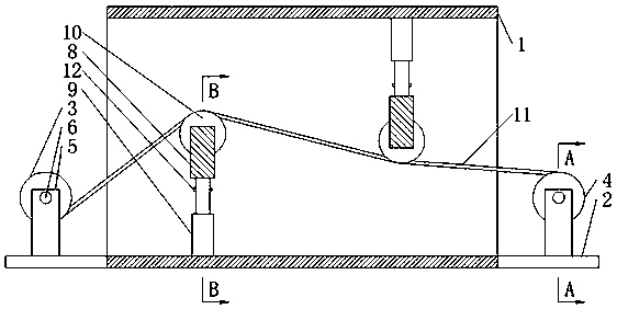
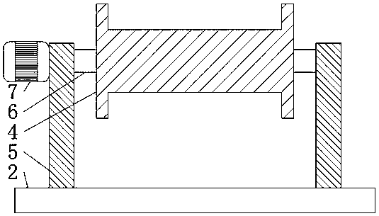
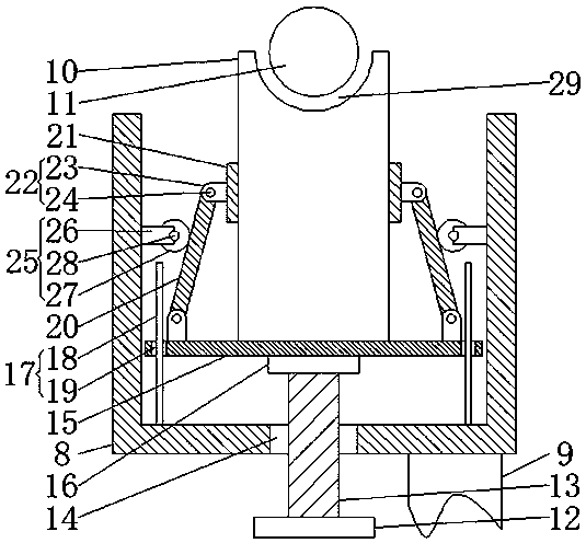
[0019] See Figure 1-3 , The present invention provides a technical solution: a wire oxide film polishing device includes a frame body 1 and a wire rod 11. The left and right sides of the frame body 1 are both openings, and both sides of the frame body 1 are fixedly connected with a bottom plate 2 near the bottom. , The tops of the two bottom plates 2 are respectively provided with a discharging roller 3 and a coiling roller 4, the front and rear sides of the discharging roller 3 and the coiling roller 4 are equipped with a fixing plate 5, and the fixing plate 5 is fixedly connected to the top of the bottom plate 2. , The inner cavities of the unwinding roller 3 and the coiling roller 4 are both provided with a rotating rod 6, and the two ends of the rotating rod 6 are respectively inserted into the adjacent fixed plate 5, which is located on the fixed plate 5 behind the coiling roller 4 A motor 7 is fixedly connected to the rear side. The rear end of the rotating rod 6 penetrates the adjacent fixed plate 5 and is fixedly connected to the power output end of the motor 7. The inner cavity of the frame 1 is provided with two support frames 8, two supports The frame 8 is arranged on the left and right, the inner side of the support frame 8 is provided with grinding wheels 10, the two ends of the wire 11 respectively extend to the outside of the frame 1, and are respectively wound on the unwinding roller 3 and the winding roller 4, and the wire 11 is connected to the The top and bottom of the two grinding wheels 10 are attached to each other. The side of the grinding wheel 10 away from the support frame 8 is provided with a groove 29, and the groove 29 matches with the wire 11, and the wire 11 is inserted into the inner cavity of the groove 29 to support The side of the frame 8 away from the grinding wheel 10 is fixedly connected with an electric telescopic rod 9, and the ends of the two electric telescopic rods 9 away from the support frame 8 are respectively fixedly connected to the top and bottom of the inner cavity of the frame 1, and the rear side of the electric telescopic rod 9 is provided There is a hand crank 12, the cross section of the support frame 8 is U-shaped, and the U-shaped opening of the support frame 8 faces away from the adjacent hand crank 12, and the hand crank 12 close to the support frame 8 is fixedly connected with threads Rod 13, the inner cavity of the support frame 8 close to the hand wheel 12 is fixedly connected with a nut 14. The support frame 8 is provided with a horizontal plate 15 on the inner side, and the horizontal plate 15 and the side of the grinding wheel 10 away from the wire 11 are attached to each other. A bearing 16 is fixedly connected to the side of the plate 15 away from the grinding wheel 10. The end of the threaded rod 13 away from the hand wheel 12 penetrates the nut 14 and is inserted into the inner cavity of the bearing 16. The upper part of the transverse plate 15 is provided near the front and rear sides. The limit mechanism 17, the limit mechanism 17 includes a vertical rod 18, the vertical rod 18 is located on the side of the horizontal plate 15 away from the grinding wheel 10, the horizontal plate 15 is provided with a limit hole 19 matching the vertical rod 18, the vertical rod 18 One end is fixedly connected to the inner wall of the support frame 8, the other end of the vertical rod 18 penetrates the limiting hole 19, the top of the horizontal plate 15 is provided with connecting rods 20 near the front and rear sides, the connecting rod 20 is inclined, and the connecting rod 20 The angle between the horizontal plate 15 and the grinding wheel 10 is an acute angle. The top end of the connecting rod 20 is provided with a clamping plate 21. Both ends of the connecting rod 20 are provided with a connecting mechanism 22. The connecting mechanism 22 includes a connecting block 23. Located at one end of the connecting rod 20, a pin shaft 24 is provided between the connecting block 23 and the connecting rod 20. The connecting block 23 and the connecting rod 20 are movably connected by the pin shaft 24. The connecting block 23 at the top of the connecting rod 20 is fixedly connected to The clamping plate 21 is on the side away from the grinding wheel 10, the connecting block 23 at the top end of the connecting rod 20 is fixedly connected to the inner wall of the support frame 8, and the side of the connecting rod 20 away from the grinding wheel 10 is provided with a movable mechanism 25. The movable mechanism 25 includes a support plate 26, which is fixedly connected to the inner wall of the support frame 8, a roller 27 is provided between the support plate 26 and the connecting rod 20, and a rotating shaft 28 is provided between the roller 27 and the support plate 26, The roller 27 is movably connected to the support plate 26 via the rotating shaft 28, and the outer edge of the roller 27 and the side of the connecting rod 20 away from the grinding wheel 10 are attached to each other.
[0020] Working principle: During use, install the grinding wheel 10 on the inner side of the support frame 8. Before installing the grinding wheel 10, turn the hand wheel 12 to increase the distance between the two splints 21, and the hand wheel 12 drives the threaded rod. 13 rotates in the inner cavity of the nut 14 and the bearing 16, the threaded rod 13 drives the cross plate 15 to move relative to the nut 14 in the direction of the adjacent electric telescopic rod 9 under the action of the thread, and then turns the connecting rod 20 in the direction of the adjacent roller 27 , The connecting rod 20 drives the clamping plates 21 to move to adjust the distance between the two clamping plates 21. When the distance between the clamping plates 21 is greater than the thickness of the grinding wheel 10 to be fixed, the grinding wheel 10 is placed on the two clamping plates 21 In between, the groove 29 is directed to the side away from the horizontal plate 15 and the grinding wheel 10 and the horizontal plate 15 are attached to each other. After that, the operator turns the splint 21, and the splint 21 is turned over with the pin axis 24 to make the side of the splint 21 The wall and the side wall of the grinding wheel 10 are attached to each other, and then the hand wheel 12 is reversely rotated, so that the horizontal plate 15 moves away from the adjacent electric telescopic rod 9, and the horizontal plate 15 moves on the outer edge of the vertical rod 18 when moving , The horizontal plate 15 drives the connecting rod 20 and the grinding wheel 10 to move. When the connecting rod 20 moves, it touches the roller 27. As the horizontal plate 15 moves, the roller 27 presses the connecting rod 20, causing the connecting rod 20 to turn in the direction of the grinding wheel 10. At the same time, the roller 27 rolls on the side wall of the connecting rod 20, and the connecting rod 20 drives the splint 21 to flip, that is, when the horizontal plate 15 wants to move away from the adjacent electric telescopic rod 9, the distance between the two splints 21 gradually changes The grinding wheel 10 is fixed in the inner cavity of the support frame 8, and then the operator passes the wire 11 to be processed through the frame 1 and winds it on the winding roller 4, and at the same time makes the wire 11 located on the two grinding wheels 10 Then the electric telescopic rod 9 is controlled to extend by the external power supply. The electric telescopic rod 9 drives the adjacent grinding wheel 10 to move, and the grinding wheel 10 moves to fit the wire 11 so that the wire 11 is clamped in the groove 29 In the inner cavity, until the wire 11 is in a stretched state, stop the electric telescopic rod 9 from working, and then start the motor 7 through the external power supply. The motor 7 drives the winding roller 4 to rotate by rotating the rod 6 to receive the material. In the process of receiving the wire 11 moves between two grinding wheels 10, and the two grinding wheels 10 respectively polish the surface of the wire from different directions, so as to remove the oxide film on the surface of the wire 11.
[0021] Although the embodiments of the present invention have been shown and described, those of ordinary skill in the art can understand that various changes, modifications, and substitutions can be made to these embodiments without departing from the principle and spirit of the present invention. And variations, the scope of the present invention is defined by the appended claims and their equivalents.

PUM

no PUM

Description & Claims & Application Information

We can also present the details of the Description, Claims and Application information to help users get a comprehensive understanding of the technical details of the patent, such as background art, summary of invention, brief description of drawings, description of embodiments, and other original content. On the other hand, users can also determine the specific scope of protection of the technology through the list of claims; as well as understand the changes in the life cycle of the technology with the presentation of the patent timeline. Login to view more.

Similar technology patents

High-temperature color developing method and device for copper oxide

PendingCN113502448AThe appearance is bright and beautifulThe device is easy to operateDecorative surface effectsSolid state diffusion coatingOxidation resistantMetal working
Owner:云南滇工李雕塑艺术有限公司

Classification and recommendation of technical efficacy words

  • Avoid polluting the environment
  • The device is easy to operate

Polyvinyl butyral foamed material

Owner:LUOHE IRON HORSE RUBBER PROD CO LTD

Precise measurement method for density of antimagnetic material

ActiveCN106568681AThe device is easy to operateLow costMaterial analysis by observing immersed bodiesPhysicsLevitation
Owner:ZHEJIANG UNIV
Why Eureka
Try Eureka