Reverse cutting process for diamond wire

A cutting process and diamond wire technology, applied in the field of diamond wire reverse cutting process, can solve the problems of poor and abnormal surface quality of the cut silicon wafer, the surface color difference of the silicon wafer entering the knife, and the texturing affecting the battery end process. Improve the problem of poor chromatic aberration, reduce the feed TTV, and improve the effect of insufficient cutting force

Inactive Publication Date: 2020-08-04
QINGDAO GAOCE TECH CO LTD
View PDF5 Cites 4 Cited by
  • Summary
  • Abstract
  • Description
  • Claims
  • Application Information

AI Technical Summary

Problems solved by technology

The process has a great influence on the quality of the cut surface of the silicon wafer, and the surface quality of the silicon wafer is an important indicator that affects the cutting yield. If the process parameters are not set properly, the surface quality of the cut silicon wafer will be poor and abnormal, resulting in a decrease in the grade of the silicon wafer and production. The cost increases, and at the same time, the poor surface quality of the silicon wafer will also affect the texturing of the subsequent battery end process
[0003] At present, many enterprises adopt tangent and anti-tangential process methods for multi-wire cutting. Both tangent and anti-tangential are cut into the knife by the old wire mesh. It is easy to have a large wire bow at the position where the knife enters, resulting in abnormal color difference on the surface of the silicon wafer where the knife enters, and Forward and reverse cutting process, when the forward cutting reaches a certain position in the middle of the silicon wafer, the reverse cutting is switched. The cutting force of the steel wire at this position is inconsistent, which may easily lead to poor color difference and TTV at the reverse cutting position of the silicon wafer, which will affect the surface quality of the silicon wafer.

Method used


Image

  • Reverse cutting process for diamond wire
  • Reverse cutting process for diamond wire

Examples


Embodiment Construction

[0028] In order to enable those skilled in the art to better understand the technical solution of the present invention, the technical solution of the present invention will be described clearly and completely below in conjunction with the accompanying drawings of the present invention. Based on the embodiments in this application, other similar embodiments obtained by those of ordinary skill in the art without creative work should fall within the protection scope of this application. In addition, the directional terms mentioned in the following embodiments, such as "up", "down", "left", "right", etc. are only the directions with reference to the drawings. Therefore, the directional terms used are used to illustrate rather than limit the text. invent.

[0029] The present invention will be further described below in conjunction with the drawings and preferred embodiments.

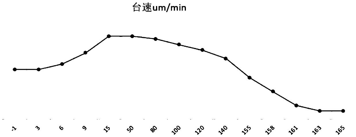
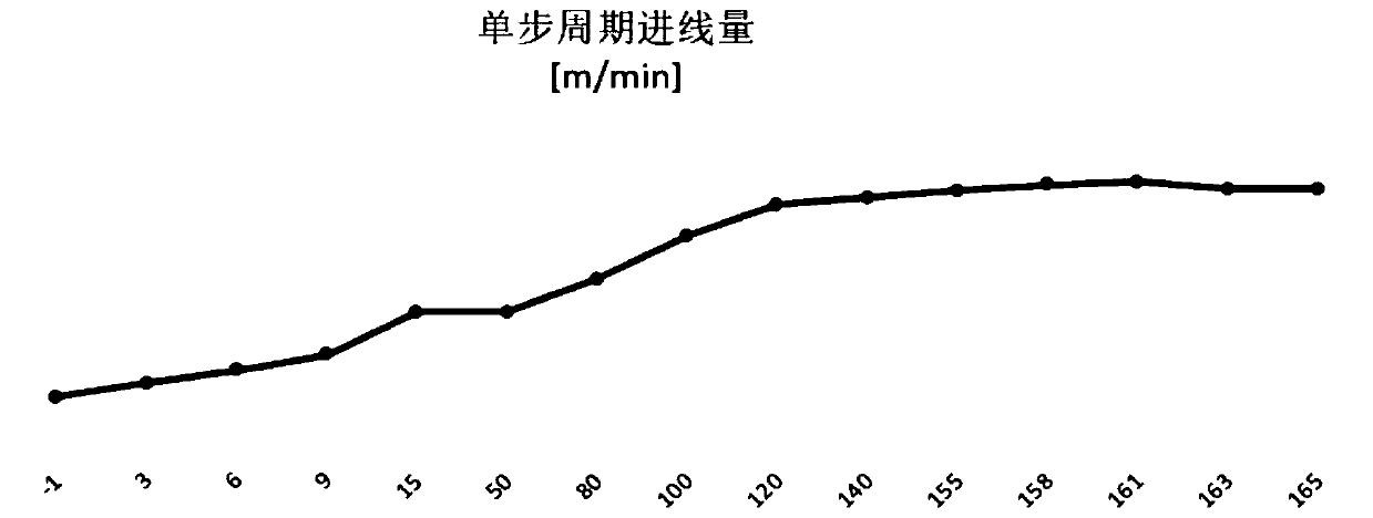
[0030] The diamond wire reverse cutting process of the present invention adopts multi-wire cutting and the c...


PUM


Abstract

The invention belongs to the technical field of diamond wire cutting, and particularly relates to a reverse cutting process for a diamond wire. The reverse cutting process comprises the following steps: selecting and cleaning a qualified crystal bar, filling the crystal bar into a clamping guide rail of a cutter workbench, adopting the diamond wire with the diameter of 45 [mu]m-60[mu]m as a cutting wire, spreading a cutting wire net, adding cooling liquid, placing the diamond wire for cutting onto a take-up wheel from a pay-off wheel, setting diamond wire operation speed to be 600 m/min-2100m/min, and setting cutting workbench feeding speed to be 200-3500 [mu]m/min, changing a cutting direction to be reverse cutting from front cutting before cutting, starting a cutter to start cutting, andtaking down the crystal bar by an unloading vehicle after cutting is accomplished. The reverse cutting process adopted by the invention is consistent in cutting direction in the whole process, improves the problem that surface quality and chromatic aberration of a silicon slice is poor, improves silicon slice surface quality, and reduces production cost.

Description

Technical field [0001] The invention belongs to the technical field of diamond wire cutting, and specifically relates to a diamond wire reverse cutting process. Background technique [0002] At present, with the multi-wire cutting of photovoltaic silicon wafers, the gradual reduction of production costs is the lifeblood of a long-term survival of enterprises, and the reduction of production costs permeates every aspect of production. The process has a great influence on the surface quality of the silicon wafer, and the surface quality of the silicon wafer is an important indicator that affects the cutting yield. Poor setting of process parameters will lead to poor surface quality of the cut silicon wafer, resulting in a reduction in silicon wafer grade and production. The cost increases, and at the same time, the poor surface quality of the silicon wafer will also affect the texturing of the subsequent battery end process. [0003] Many companies currently use tangent and forward-...

Claims


Application Information

Patent Timeline
Patent Type & Authority Applications(China)
IPC IPC(8): B28D5/04
CPCB28D5/0064B28D5/045
Inventor 刘云强邢旭唐亮
Owner QINGDAO GAOCE TECH CO LTD
Why Eureka
Try Eureka