
A Bundle Optical Cable Sheath Extrusion Production Line

A production line and optical cable technology, applied in the field of bundled optical cable sheath extrusion production line, can solve the problems of optical cable production speed block, optical cable surface is not easy to have water residue, optical cable with water, etc., to achieve the effect of improving the cooling effect

Active Publication Date: 2021-05-28
TAKFLY COMM
View PDF1 Cites 0 Cited by
  • Summary
  • Abstract
  • Description
  • Claims
  • Application Information

AI Technical Summary

Problems solved by technology

[0004] However, after the optical cable is water-cooled, the water in the water tank will be carried on the surface when it comes out of the water tank, which is not conducive to the subsequent processing of the optical cable. The patent discloses a production line for cable synthesis, sheath production, sheath cooling, and sheath air drying. In this production line, a cable blower is used to dry the optical cable coming out of the water tank, so that the surface of the optical cable is not prone to water. residues for subsequent processing
[0005] The above-mentioned existing technical solutions have the following defects: the production speed of the optical cable is relatively fast, so it is difficult for the optical cable to be dried quickly when passing through the cable blower, which is prone to appear on the surface of the optical cable even after passing through the cable blower. The water residue is not conducive to the subsequent processing of optical cables, so it needs to be improved

Method used


Image

  • A Bundle Optical Cable Sheath Extrusion Production Line
  • A Bundle Optical Cable Sheath Extrusion Production Line
  • A Bundle Optical Cable Sheath Extrusion Production Line

Examples


Embodiment 2

[0056] Embodiment two, refer to Figure 4 , the difference from Embodiment 1 is that a liquid collection tank 51 is arranged below the junction of the liquid inlet pipe 5 and or the liquid outlet pipe 6 and the connecting pipe 72. The liquid collection tank 51 is in the shape of a rectangular parallelepiped and is made of stainless steel. The upper end of the liquid tank 51 is open, and the liquid collecting tank 51 is welded to the lower surface of the liquid inlet pipe 5 and or the axial side of the liquid outlet pipe 6. Once the cooling liquid seeps out, the cooling liquid is not easy to drop directly on the ground.

Embodiment 3

[0057] Embodiment three, refer to figure 1 and Figure 5 , the difference from Embodiment 1 is that a plurality of driving parts 321 are fixed by bolts on the mounting table 32, and the driving parts 321 are servo motors, and a driving part 321 is arranged under each liquid inlet pipe 5, A pinion 3211 is sheathed on the output shaft of the driver 321, and the pinion 3211 is keyed to the output shaft of the driver 321, and a pinion 3211 is sleeved on the outer surface of each connecting pipe 72 connected to the liquid inlet pipe 5. The large gear 721 is keyed to the connecting pipe 72, and a large gear 721 is correspondingly meshed with a small gear 3211, so that when the output shaft of a driver 321 rotates, it can drive a connecting pipe 72 to rotate, and then drive a The cooling wheel 31 rotates. In a cooling mechanism 3, the upper and lower cooling wheels 31 turn in the opposite direction, and when the two cooling wheels 31 rotate, they will not hinder the movement of the ...


PUM


Abstract

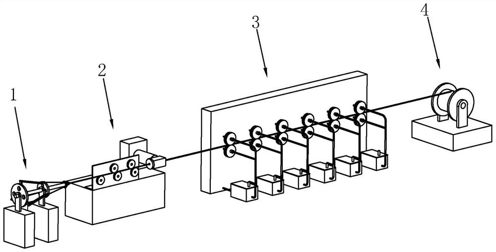
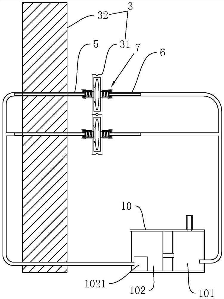
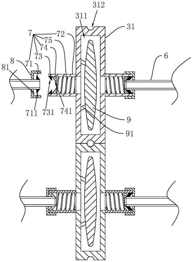
The invention relates to a production line for sheath extrusion of bundled optical cables. The axes of the cooling wheels are parallel, the optical cable passes between the two cooling wheels, and the surface of the optical cable abuts against the ends of the shaft side surfaces of the two cooling wheels that are close to each other; the inside of the cooling wheel is provided with a cavity, which is used to accommodate the cooling of the optical cable. cooling liquid; one side surface of the cooling wheel is provided with a liquid inlet pipe, and one end of the liquid inlet pipe is connected with the cavity; the other side surface of the cooling wheel is provided with a liquid outlet pipe, and one end of the liquid outlet pipe is also connected with the cavity; A sealing assembly is provided at the connection between the liquid pipe and the cooling wheel and the connection between the liquid outlet pipe and the cooling wheel. The invention can prevent the optical cable from contacting with water while water cooling, effectively prevents the cooling water from adhering to the surface of the optical cable, and facilitates the continued processing of the optical cable after it is cooled and shaped.

Description

technical field [0001] The invention relates to the technical field of optical cable production, in particular to a bundled optical cable sheath extrusion production line. Background technique [0002] An optical cable is a communication cable assembly that uses one or more optical fibers placed in a sheath as a transmission medium and can be used individually or in groups. [0003] The existing optical cable production process mainly includes the following steps. Take the optical cable composed of multiple optical fibers as an example. First, the multiple optical fibers need to be twisted into one, and then the synthetic optical fiber is wrapped on the surface by an extruder. A layer of rubber sheath forms a complete optical cable. The complete optical cable needs to be cooled and shaped after it comes out of the extruder; the general cooling and setting method is mainly to use water cooling, that is, the optical cable coming out of the extruder needs to pass through a bear...

Claims


Application Information

Patent Timeline
Patent Type & Authority Patents(China)
IPC IPC(8): G02B6/44
CPCG02B6/4479G02B6/4486
Inventor 刘合一
Owner TAKFLY COMM
Learn More