Composite liquid cooling heat dissipation plate

A liquid-cooling and heat-dissipating, composite technology, applied in the direction of cooling/ventilation/heating transformation, electrical components, electrical equipment structural parts, etc., can solve the problems of inconvenient maintenance and replacement of sealing rubber rings, uneven heat dissipation, small contact area, etc. Achieve optimization of friction stir welding and welding parameters, best welding fusion effect, and increase the effect of contact area

Active Publication Date: 2020-08-04
湖南意华交通装备股份有限公司
View PDF3 Cites 0 Cited by
  • Summary
  • Abstract
  • Description
  • Claims
  • Application Information

AI Technical Summary

Problems solved by technology

The mainstream method in the prior art is to separately process the electric control housing and the radiator and then assemble them together with sealing rubber rings. Since the radiator is generally water-cooled and heat-dissipated, this method is prone to leakage risks , and the inconvenience caused by the maintenance and replacement of the sealing rubber ring after long-term use
In addition, the thermal conductivity of the existing electronic control housing and radiator materials is low, and it is gradually difficult to meet the high integration and high power consumption IGBT liquid cooling requirements, and the casting of the electronic control housing has a draft angle, resulting in the minimum The liquid contact area at the end is small, which leads to uneven heat dissipation

Method used


Image

  • Composite liquid cooling heat dissipation plate
  • Composite liquid cooling heat dissipation plate
  • Composite liquid cooling heat dissipation plate

Examples


Embodiment Construction

[0027] In order to make the technical problems, technical solutions and advantages to be solved by the present invention clearer, the following will describe in detail with reference to the drawings and specific embodiments. Apparently, the described embodiments are some, but not all, embodiments of the present invention. Based on the embodiments of the present invention, all other embodiments obtained by persons of ordinary skill in the art without making creative efforts belong to the protection scope of the present invention.

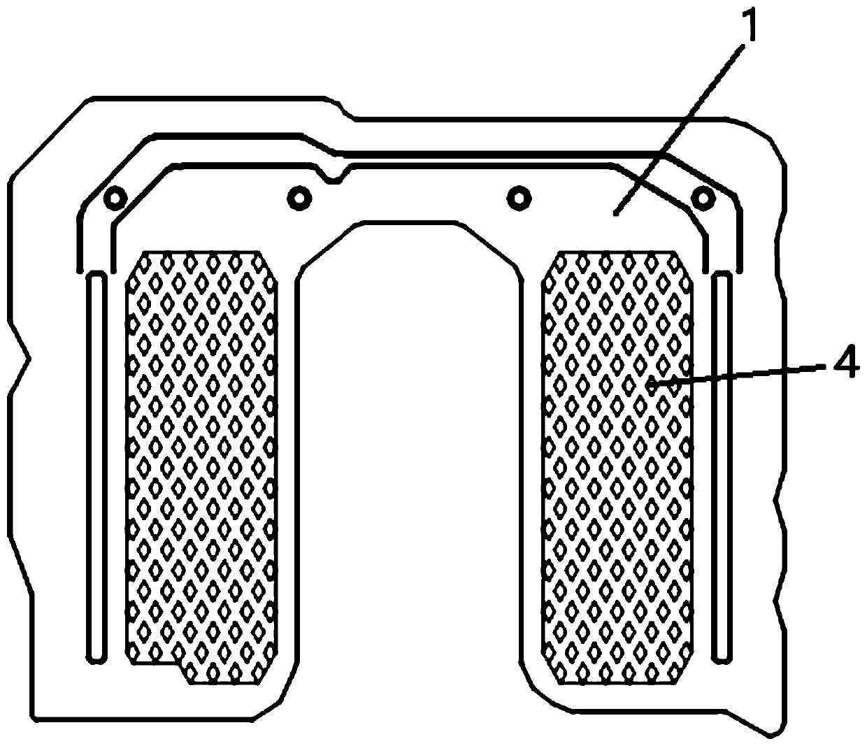
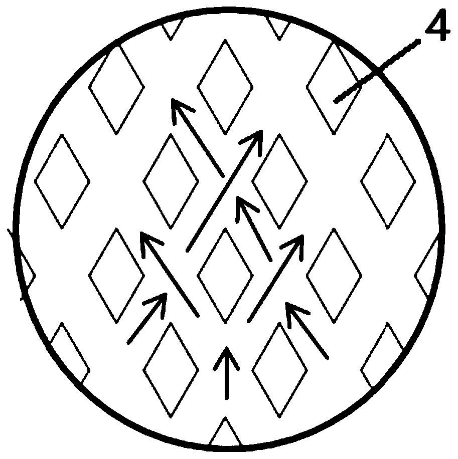
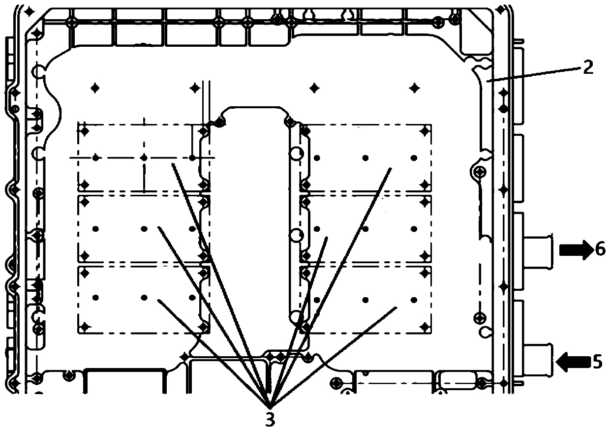
[0028] Such as Figure 1-Figure 3 As shown, the embodiment of the present invention provides a composite liquid-cooled radiator plate 1, which is arranged in the electronic control housing 2 of a new energy electric vehicle, and the composite liquid-cooled radiator plate 1 and the heat source 3 of the electronic control housing 2 The back side is welded as a whole to form a sealed space for cooling liquid to flow. At the same time, the composite liq...


PUM


Abstract

The invention provides a composite liquid cooling heat dissipation plate. The combined type liquid cooling heat dissipation plate is arranged in an electric control shell of a new energy electric vehicle, the combined type liquid cooling heat dissipation plate and the back face of a heat source of the electric control shell are integrally welded in a friction mode to form a sealed space where cooling liquid flows, and protruding structures which are regularly arranged are arranged on the combined type liquid cooling heat dissipation plate according to the flow direction of the cooling liquid to form a flow channel of the cooling liquid. According to the composite liquid cooling heat dissipation plate, the space of the electric control shell is effectively utilized, the contact area betweencooling liquid and the heat dissipation plate and the contact area between the cooling liquid and the electric control shell are increased through the cooling liquid flow channel formed in the sealedspace by the protruding structures arranged on the composite liquid cooling heat dissipation plate, better heat dissipation effect is achieved, and the cooling liquid leakage risk and the structure maintenance cost are reduced.

Description

technical field [0001] The invention relates to the technical field of heat dissipation for new energy electric vehicles, in particular to a composite liquid-cooled heat dissipation plate. Background technique [0002] At present, new energy electric vehicles are on the rise, and their electronic control housings are becoming more and more highly integrated, and the power consumption of the IGBTs in the electronic control housings is also increasing. While the degree of integration continues to increase, heat dissipation must also be considered. The mainstream method in the prior art is to separately process the electric control housing and the radiator and then assemble them together with sealing rubber rings. Since the radiator is generally water-cooled and heat-dissipated, this method is prone to leakage risks , and the inconvenience caused by the maintenance and replacement of the sealing rubber ring after long-term use. In addition, the thermal conductivity of the exis...

Claims


Application Information

Patent Timeline
Patent Type & Authority Applications(China)
IPC IPC(8): H05K7/20
CPCH05K7/20872H05K7/20927Y02E60/10
Inventor 彭云华康乐曾志勇
Owner 湖南意华交通装备股份有限公司
Why Eureka
Try Eureka