Self-snow-removing greenhouse structure

A technology for greenhouses and roof panels, which is used in greenhouse cultivation, snow traps, building structures, etc., can solve the problems of temperature and light intensity drop, collapse, slow melting of snow, etc., so as to improve production effect and improve light transmission. effect, effect of avoiding damage

Active Publication Date: 2020-08-07
湖州亿源科技发展有限公司
View PDF8 Cites 3 Cited by
  • Summary
  • Abstract
  • Description
  • Claims
  • Application Information

AI Technical Summary

Problems solved by technology

[0003] However, in winter, especially in the colder north, there are often heavy snowfalls, blizzards and other weather. Since the greenhouses are mostly built with plastic films or glass panels, they are easily crushed if covered by a large amount of snow, resulting in the loss of

Method used


Image

  • Self-snow-removing greenhouse structure
  • Self-snow-removing greenhouse structure
  • Self-snow-removing greenhouse structure

Examples


Embodiment 1

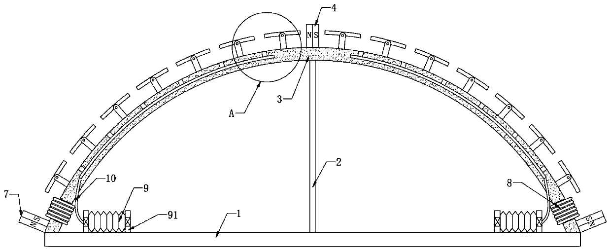
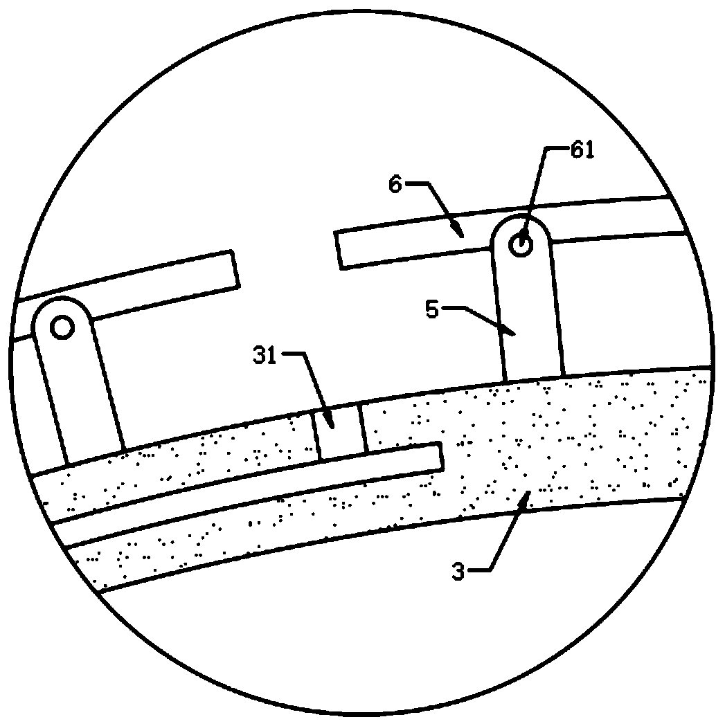
[0021] refer to Figure 1-2 , a self-removing snow greenhouse structure, comprising a base 1, the upper end of the base 1 is welded with a support rod 2, the upper end of the support rod 2 is provided with a roof plate 3, and the upper end of the roof plate 3 is provided with a first electromagnet 4, Both sidewalls of the ceiling board 3 are provided with a second electromagnet 7, and the first electromagnet 4 and the second electromagnet 7 are opposite to each other when they are energized. The side wall of 5 is rotatably connected with snow shield 6 through spring shaft 61, and snow shield 6 is made of silicon steel sheet.

[0022] It should be noted that no matter what the direction of the magnetic field is, the snow shield 6 is made of silicon steel sheets, and its magnetization direction always obeys the external magnetic field. During the negative peak value, the magnitude and direction of the magnetic force formed for the snow shield 6 are consistent, and the magnetic ...

Embodiment 2

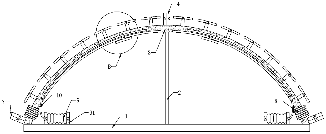
[0031] refer to Figure 3-4 The difference from the first embodiment is that a brush board 11 is slidably connected to the side wall of the ceiling board 3, the brush board 11 is made of magnetic material, and a sponge strip is fixedly connected to the brush board 11.

[0032] Specifically, a guide groove 32 is provided on the inner side wall of the ceiling board 3 , and a guide block 111 is slidably connected in the guide groove 32 , and the lower end of the guide block 111 is fixedly connected with the brush plate 11 .

[0033] In this embodiment, when the current direction leading to the first electromagnet 4 and the second electromagnet 7 changes, the magnetic poles of the first electromagnet 4 and the second electromagnet 7 also change accordingly, and because the first electromagnet 4. It is opposite to the opposite magnetic pole of the second electromagnet 7, so that under the action of magnetic force, the brush plate 11 made of magnetic material can slide back and fort...


PUM


Abstract

The invention discloses a self-snow-removing type greenhouse structure which comprises a base, a supporting rod is welded to the upper end of the base, a greenhouse top plate is arranged at the upperend of the supporting rod, a first electromagnet is arranged at the upper end of the greenhouse top plate, and second electromagnets are arranged on the two side walls of the greenhouse top plate. Theopposite magnetic poles of the first electromagnet and the second electromagnet are opposite when the first electromagnet and the second electromagnet are powered on, a plurality of ejector rods arefixedly connected to the greenhouse top plate, the side walls of the ejector rods are rotationally connected with snow baffles through spring shafts, and the snow baffles are composed of silicon steelsheets. Current is generated through the thermoelectric power generation set and is converted into alternating current with the direction and the size changing continuously under the action of the inverter, so that the magnetic field between the first electromagnet and the second electromagnet changes continuously accordingly, the stress direction of each snow baffle changes continuously, and thesnow baffles can shake back and forth along the rotating axes of the snow baffles; therefore, accumulated snow covering the snow blocking plate can be shaken off, and damage of the accumulated snow to the greenhouse is avoided.

Description

technical field [0001] The invention relates to the technical field of agricultural equipment, in particular to a self-snow-removing greenhouse structure. Background technique [0002] The greenhouse uses light-transmitting covering materials as all or part of the enclosure structure, which is used to ensure the normal growth and development of crops in the cold winter. [0003] However, in winter, especially in the colder north, there are often heavy snowfalls, blizzards and other weather. Since the greenhouses are mostly built with plastic films or glass panels, they are easily crushed if covered by a large amount of snow, resulting in the loss of crops in the greenhouses. die. In addition, the snow melts slowly. Before the snow melts, the sunlight entering the greenhouse is weak, which leads to a decrease in the temperature and light intensity in the greenhouse, which seriously affects the growth of plants in the greenhouse. Contents of the invention [0004] The obje...

Claims


Application Information

Patent Timeline
IPC IPC(8): A01G9/14E04D13/10B08B1/00
CPCA01G9/14A01G2009/1492B08B1/002E04D13/106Y02A40/25
Inventor 曹剑
Owner 湖州亿源科技发展有限公司
Why Eureka
Try Eureka