Cooking utensil

A technology of cooking utensils and cooking utensils, which is applied in the direction of steam cooking utensils, cooking utensils, cooking utensils/covers, etc., and can solve the problems of low heat utilization rate and impact

Pending Publication Date: 2020-08-07
GREE ELECTRIC APPLIANCES INC
View PDF0 Cites 0 Cited by
  • Summary
  • Abstract
  • Description
  • Claims
  • Application Information

AI Technical Summary

Problems solved by technology

[0004] Therefore, the technical problem to be solved by the present invention is to overcome the defects that the heat in the cooking utensils in the prior art affects the devices on the casing and the heat utilization rate is low.

Method used


Image

  • Cooking utensil
  • Cooking utensil
  • Cooking utensil

Examples


Embodiment

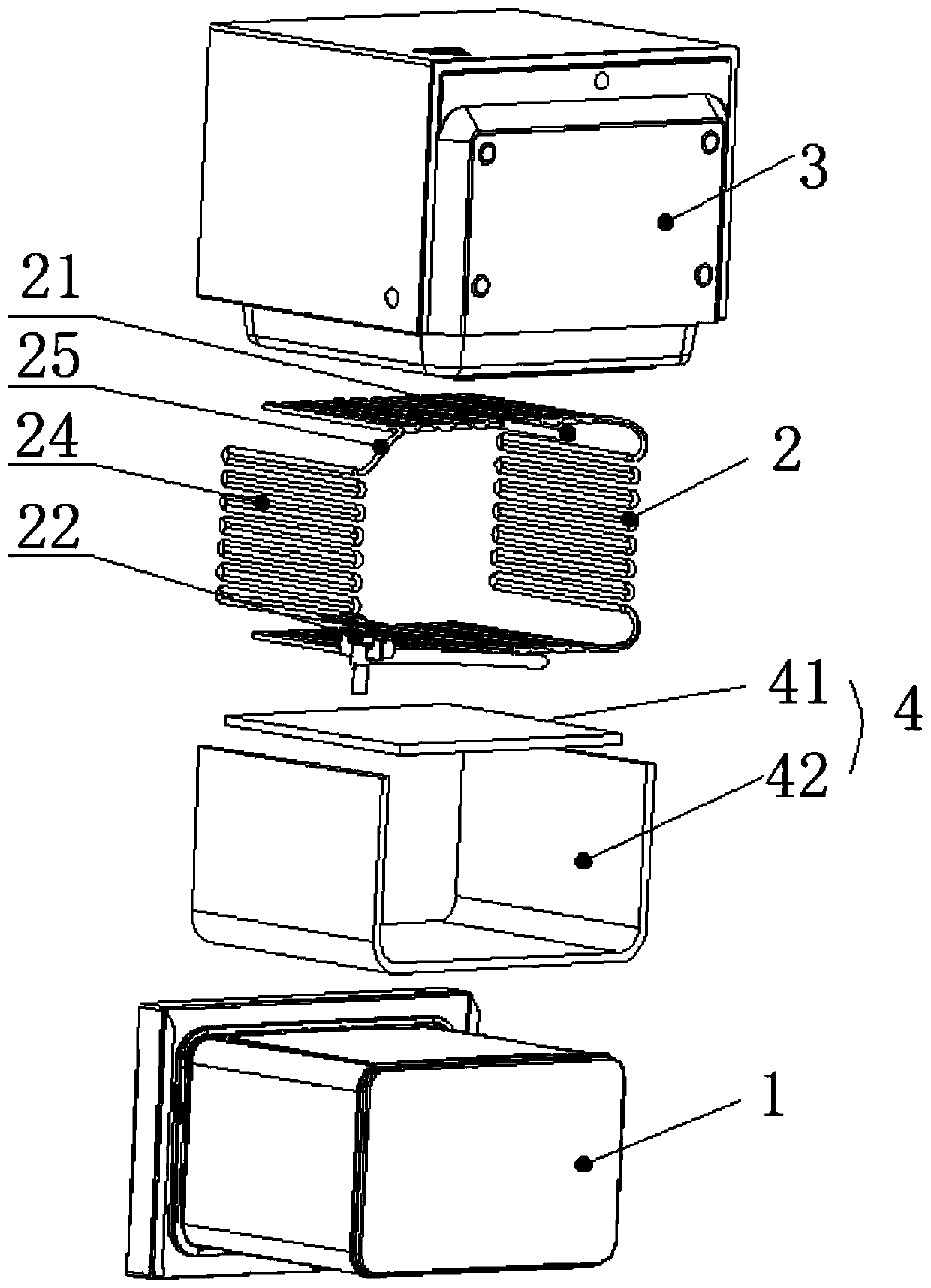
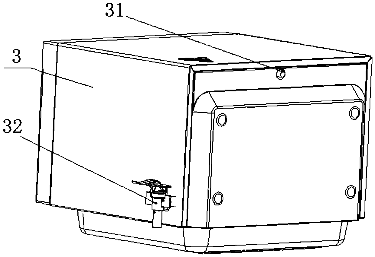
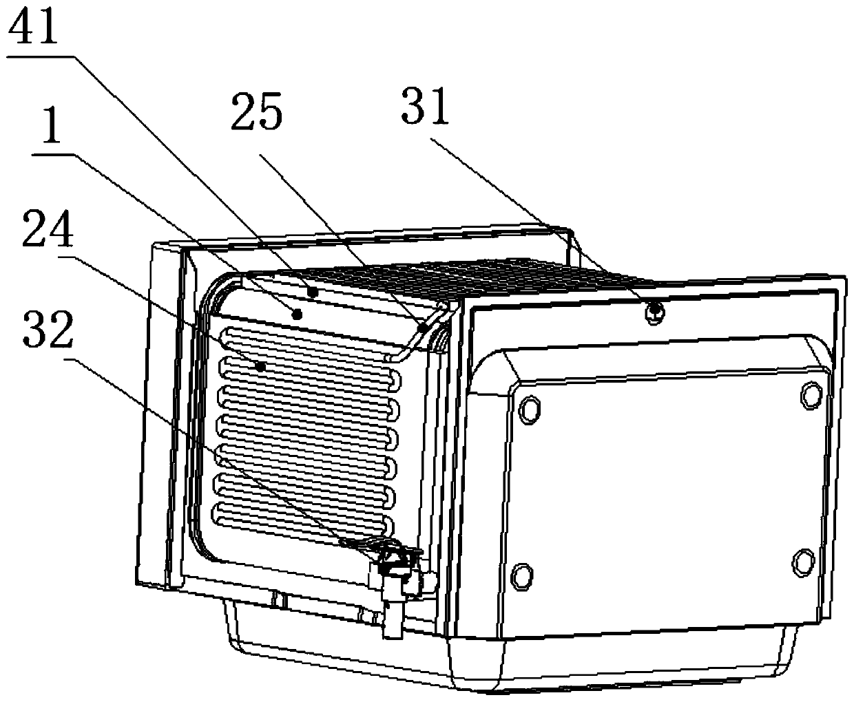
[0043] This embodiment provides a cooking utensil, which can be an oven, a steamer, or an integrated steaming and baking machine, such as Figure 1-Figure 8 shown, including:

[0044] The furnace 1 is provided with a space suitable for placing ingredients inside, and the furnace 1 itself is made of metal material, such as stainless steel. An opening is provided on the furnace 1, and a door body suitable for closing or opening the opening is provided on the opening. A sealing ring is provided on the corresponding part of the door body and the opening. 1, so as to avoid heat, etc. from escaping through the opening;

[0045]The waterway plate 2 is arranged on the outer wall of the furnace 1, and the waterway plate 2 is provided with a first water inlet 21 and a first water outlet 22. In this embodiment, the first water inlet 21 is suitable for receiving external water sources , the cooling water entering through the first water inlet 21 flows through the water channel plate 2 a...


PUM


Abstract

The invention provides a cooking utensil. According to the cooking utensil, a waterway plate is arranged between a furnace pipe and an outer frame, the waterway plate can guide external cooling waterinto the waterway plate through a first water inlet, the cooling water further acts on the furnace pipe so as to absorb heat on the furnace pipe, and the generated hot water can be further dischargedout of the cooking utensil through a first water outlet and a second water outlet. By means of the structure, cooling operation of the furnace pipe can be achieved firstly, and then devices on the outer wall of the furnace pipe can be prevented from being damaged by high temperature; and secondly, by arranging the waterway plate, redundant heat can be transferred into cooling water, the temperature of the heated cooling water is increased, subsequent use can be conducted, and thus the heat utilization rate in the furnace pipe is effectively increased.

Description

technical field [0001] The invention relates to the technical field of cooking utensils, in particular to a cooking utensil capable of producing hot water by itself. Background technique [0002] With the continuous development of people's lives, steam ovens have gradually entered people's kitchens. The steam oven generates heat through the heat pipes arranged inside, and at the same time heats the ingredients inside the steam oven. [0003] In the prior art, in order to achieve rapid heat dissipation, the outer casing of the steamer and oven is often made of metal material, which has a higher heat dissipation efficiency, and devices with different functions are often arranged on the outer surface of the outer casing. For this reason, fans are often used in the prior art for heat dissipation, but the heat dissipation efficiency of the fans is relatively low, resulting in a large amount of heat still acting on the components of the housing, and dissipated into the outside at...

Claims


Application Information

Patent Timeline
Patent Type & Authority Applications(China)
IPC IPC(8): A47J37/06A47J36/36A47J36/00A47J27/04
CPCA47J27/04A47J36/00A47J36/36A47J37/0623
Inventor 曾庆斌王大维张凯
Owner GREE ELECTRIC APPLIANCES INC
Why Eureka
Try Eureka