Postpartum auxiliary recovery device
A technology that assists recovery and seating, and is used in massage aids, physiotherapy, roller massage, etc.
- Summary
- Abstract
- Description
- Claims
- Application Information
AI Technical Summary
Problems solved by technology
Method used
Image
Examples
specific Embodiment approach 1
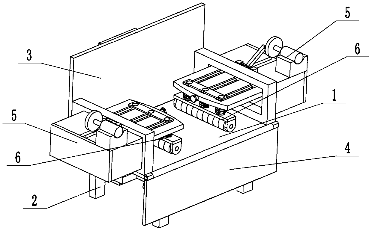
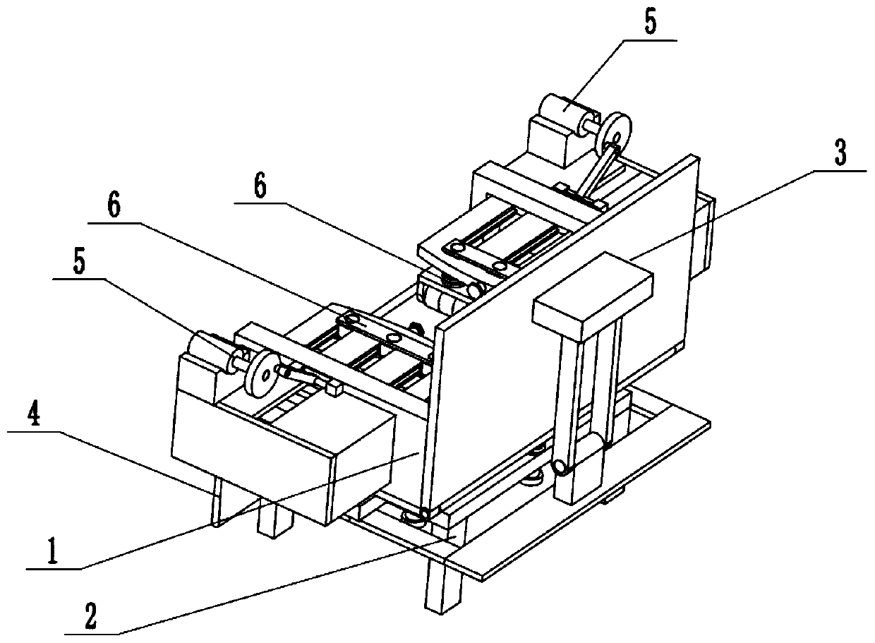
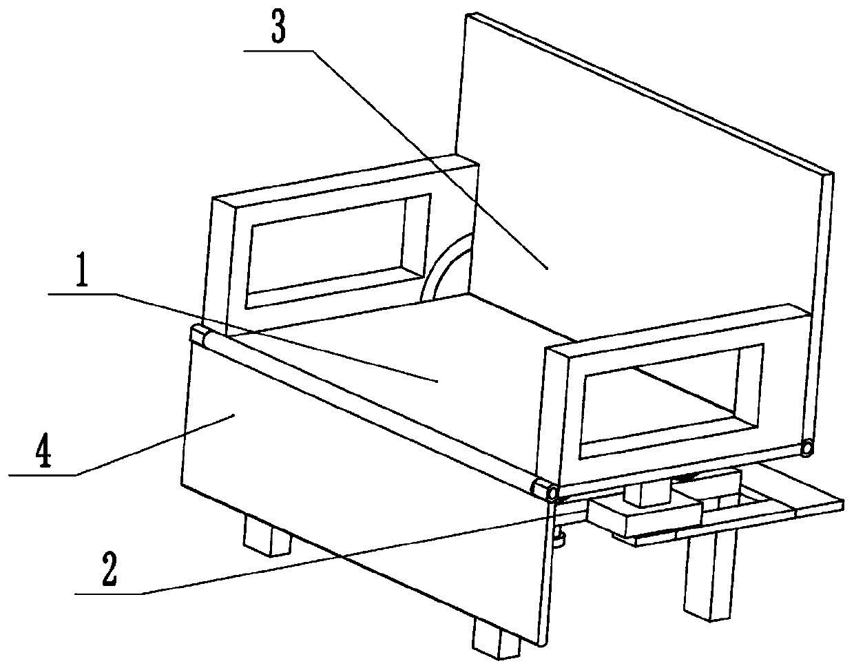
[0029] Such as Figure 1 to Figure 10As shown, a postpartum auxiliary recovery device includes a support seat 1, a seat support seat 2, a chair board 3, a foot plate 4, two pregnancy removal drivers 5 and two massagers 6, and the support seat 1 is longitudinally slidably connected to the seat support seat 2, the seat back plate 3 and the foot lift plate 4 are respectively rotatably connected to the front and rear ends of the support seat 1, the seat back plate 3 is slidably connected to the support seat 1, and the seat support seat The rear end of 2 is hinged to the chair board 3, the front end of the seat support seat 2 is hinged to the chair board 3, the two pregnancy removal drivers 5 are respectively slidably connected to the two ends of the support seat 1, and the two massagers 6 are respectively slidably connected to the Two removal gravid drives within 5. During postpartum pregnant women’s health care, provide a fast reclining chair. When sitting on the support seat 1,...
specific Embodiment approach 2
[0031] Such as Figure 1 to Figure 10 As shown, this embodiment will further describe Embodiment 1. The support seat 1 includes a seat plate 1-1, two rotating seats 1-2, two armrests 1-3, and two sliding slots 1 -4, two arc-shaped grooves 1-5 and inner arc-shaped groove 1-6, the left and right ends of the seat plate 1-1 are respectively fixedly connected with two hand platforms 1-3, and the front and rear ends of the seat plate 1-1 The two swivel seats 1-2 are respectively fixedly connected, and the two hand-held platforms 1-3 are provided with sliding slots 1-4 that penetrate left and right, and the two arc-shaped grooves 1-5 are respectively arranged on the hand-held platforms 1-3 On the front side of the inner wall, the inner wall of the arc groove 1-5 is provided with an inner arc groove 1-6.
specific Embodiment approach 3
[0033] Such as Figure 1 to Figure 10 As shown, this embodiment will further describe the second embodiment, the support seat 1 also includes a plurality of spring shafts 1-7, a plurality of spring baffles 1-8, a plurality of distribution springs 1-9, a central spring Shaft 1-10, central spring 1-11, central connecting seat 1-12, driving rack 1-13, two rectangular sliding blocks 1-14, connecting platform 1-15, front hinged seat 1-16 and front hinged shaft 1-17, the lower end of the seat plate 1-1 is evenly and fixedly connected to multiple spring shafts 1-7, the lower end of the spring shaft 1-7 is fixedly connected to the spring baffle 1-8, and the distribution spring 1-9 is socketed on the spring shaft 1- 7, the center of the lower end of the seat plate 1-1 is fixedly connected to the central spring shaft 1-10, the central spring 1-11 is sleeved on the spring shaft 1-10, and the central connecting seat 1-12 is fixedly connected to the spring shaft 1-10. At the lower end, th...
PUM
 Abstract
Description
Claims
Application Information
 - R&D
- Intellectual Property
- Life Sciences
- Materials
- Tech Scout
- Unparalleled Data Quality
- Higher Quality Content
- 60% Fewer Hallucinations
Browse by: Latest US Patents, China's latest patents, Technical Efficacy Thesaurus, Application Domain, Technology Topic, Popular Technical Reports.
© 2025 PatSnap. All rights reserved.Legal|Privacy policy|Modern Slavery Act Transparency Statement|Sitemap|About US| Contact US: help@patsnap.com


