Vibrating screen plate fixing device

A fixed device, vibrating screen technology, applied in vibration suppression adjustment, filter screen, solid separation and other directions, can solve the problems of inconvenient maintenance and replacement, inconvenient disassembly and assembly of vibrating screen, affecting the screening effect, etc., to achieve easy maintenance and replacement, thinking Clear and fast filtering effect

Inactive Publication Date: 2020-08-07
淮北良信矿山机器有限公司
View PDF0 Cites 0 Cited by
  • Summary
  • Abstract
  • Description
  • Claims
  • Application Information

AI Technical Summary

Problems solved by technology

[0003] However, some existing vibrating screens still have certain deficiencies in use. When in use, the vibrating screens are inconvenient to disassemble, repair and replace, which will affect the screening effect in the later stage. During the working process of the vibrating screen, there is a lot of noise, which needs to be improved

Method used


Image

  • Vibrating screen plate fixing device
  • Vibrating screen plate fixing device
  • Vibrating screen plate fixing device

Examples


Embodiment 1

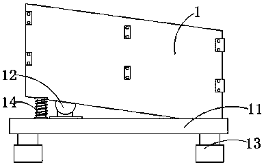
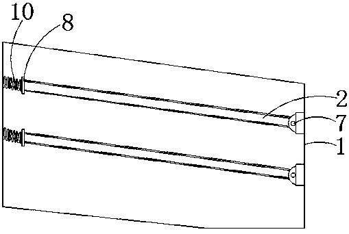
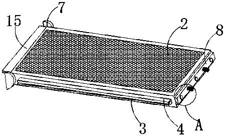
[0025] Such as Figure 1-5 As shown, a vibrating screen sieve plate fixing device includes a vibrating screen body 1 and a screen mesh 2. The inner wall of the vibrating screen body 1 is provided with a first slot 3 in parallel, and the left and right sides of the screen mesh 2 are provided with a second slot. Two draw-in slots 4, and the first draw-in slot 3 and the second draw-in slot 4 cooperate with each other, an elastic ball 5 is arranged between the upper end surface of the first draw-in slot 3 and the lower end surface of the second draw-in slot 4, the first draw-in slot 3 The limit plate 6 is fixedly arranged at the end of the limit plate 6, and the inner side wall of the limit plate 6 is in contact with the second card slot 4, the screen 2 is inclined to the left and right, and the end of the screen 2 at the bottom is rotated by the rotating shaft 7 Installed on the inner wall of the vibrating screen body 1, the screen 2 is located at a high position with a connectin...

Embodiment 2

[0028] Such as Figure 1-7 As shown, a vibrating screen sieve plate fixing device includes a vibrating screen body 1 and a screen mesh 2. The inner wall of the vibrating screen body 1 is provided with a first slot 3 in parallel, and the left and right sides of the screen mesh 2 are provided with a second slot. Two draw-in slots 4, and the first draw-in slot 3 and the second draw-in slot 4 cooperate with each other, an elastic ball 5 is arranged between the upper end surface of the first draw-in slot 3 and the lower end surface of the second draw-in slot 4, the first draw-in slot 3 The limit plate 6 is fixedly arranged at the end of the limit plate 6, and the inner side wall of the limit plate 6 is in contact with the second card slot 4, the screen 2 is inclined to the left and right, and the end of the screen 2 at the bottom is rotated by the rotating shaft 7 Installed on the inner wall of the vibrating screen body 1, the screen 2 is located at a high position with a connectin...


PUM


Abstract

The invention provides a vibrating screen plate fixing device, and relates to the field of vibrating screen devices. The vibrating screen plate fixing device comprises a vibrating screen body and a screen net, first clamping grooves are formed in the inner side wall of the vibrating screen body in parallel, second clamping grooves are formed in the left side and the right side of the screen net, elastic balls are arranged between the upper end faces of the first clamping grooves and the lower end faces of the second clamping grooves, a connecting plate is arranged at one end of the screen net,springs are fixedly arranged between the connecting plate and the inner side wall of the vibrating screen body, a supporting bottom plate is arranged at the lower end of the vibrating screen body, and a damping assembly is arranged between the vibrating screen body and the supporting bottom plate. Through the arrangement of the first clamping grooves and the second clamping grooves, the left sideand the right side of the screen net can be connected with the inner side wall of the vibrating screen body, through the arrangement of the connecting plate, the upper end of the screen net and the vibrating screen body can be detachably mounted, overhauling and replacement are facilitated, the whole device is easy to operate, clear in thought, capable of rapidly screening raw materials, and highin practicability, and the screening quality is ensured.

Description

technical field [0001] The invention relates to the field of vibrating screen devices, in particular to a vibrating screen plate fixing device. Background technique [0002] The vibrating screen uses the principle of vibrating motor excitation to make the material be thrown up on the screen surface, and at the same time move forward in a straight line to match the screen mesh reasonably to achieve the purpose of screening. Vibrating screening equipment can be divided into mining vibrating screens, light fine vibrating screens, and experimental vibrating screens according to their weight. [0003] However, some existing vibrating screens still have certain deficiencies in use. When in use, the vibrating screens are inconvenient to disassemble, repair and replace, which will affect the screening effect in the later stage. During the working process of the vibrating screen, the noise is relatively large, which needs to be improved. Contents of the invention [0004] The obj...

Claims


Application Information

Patent Timeline
Patent Type & Authority Applications(China)
IPC IPC(8): B07B1/34B07B1/46F16F15/067
CPCB07B1/343B07B1/46B07B1/4609F16F15/067
Inventor 薛敬文王勇李良宾
Owner 淮北良信矿山机器有限公司
Why Eureka
Try Eureka