Round steel polishing machining device

A processing device and round steel technology, which is applied to grinding drive devices, metal processing equipment, grinding/polishing equipment, etc., can solve the problems of surface roughness reduction, reduction of workpiece surface smoothness, workpiece traces, etc., to improve polishing The effect of efficiency

Active Publication Date: 2020-08-07
抚州市圣航洁具有限公司
View PDF6 Cites 2 Cited by
  • Summary
  • Abstract
  • Description
  • Claims
  • Application Information

AI Technical Summary

Problems solved by technology

Although this method can remove the oxide or rust on the surface, many small pits will be formed on the surface of the workpiece, and the surface roughness will be reduced, which will affect the product quality.
Now there is also a polishing machine for polishing to polish the outer surface of the round steel, but the polishing wheels of the existing polishing machine are manually pressed, which is prone to trembling, which makes the surface of the workpiece form many marks and reduces the surface smoothness of the workpiece. , affecting the quality of the product

Method used


Image

  • Round steel polishing machining device
  • Round steel polishing machining device
  • Round steel polishing machining device

Examples


specific Embodiment approach 1

[0030] Such as Figure 1-11 As shown, a round steel polishing processing device includes a bracket 1, a guide wheel mechanism 2, a moving mechanism 3, an adjusting lift mechanism 4, a polishing power frame 5, a rotating mechanism 6, a tightening mechanism 7, a tensioning mechanism 8 and a polishing mechanism 9. The guide wheel mechanism 2 is provided with two, the two guide wheel mechanisms 2 are both connected to the bracket 1, the adjusting lifting mechanism 4 is connected to the upper end of the bracket 1, and the moving mechanism 3 is connected to the adjusting On the lifting mechanism 4, the moving mechanism 3 is slidably connected to the bracket 1. The moving mechanism 3 is located between the two guide wheel mechanisms 2, the polishing power frame 5 is connected to the right end of the bracket 1, and the rotating mechanism 6 is connected in transmission On the polishing power frame 5, the tightening mechanism 7 is connected to the rotating mechanism 6, the tensioning mec...

specific Embodiment approach 2

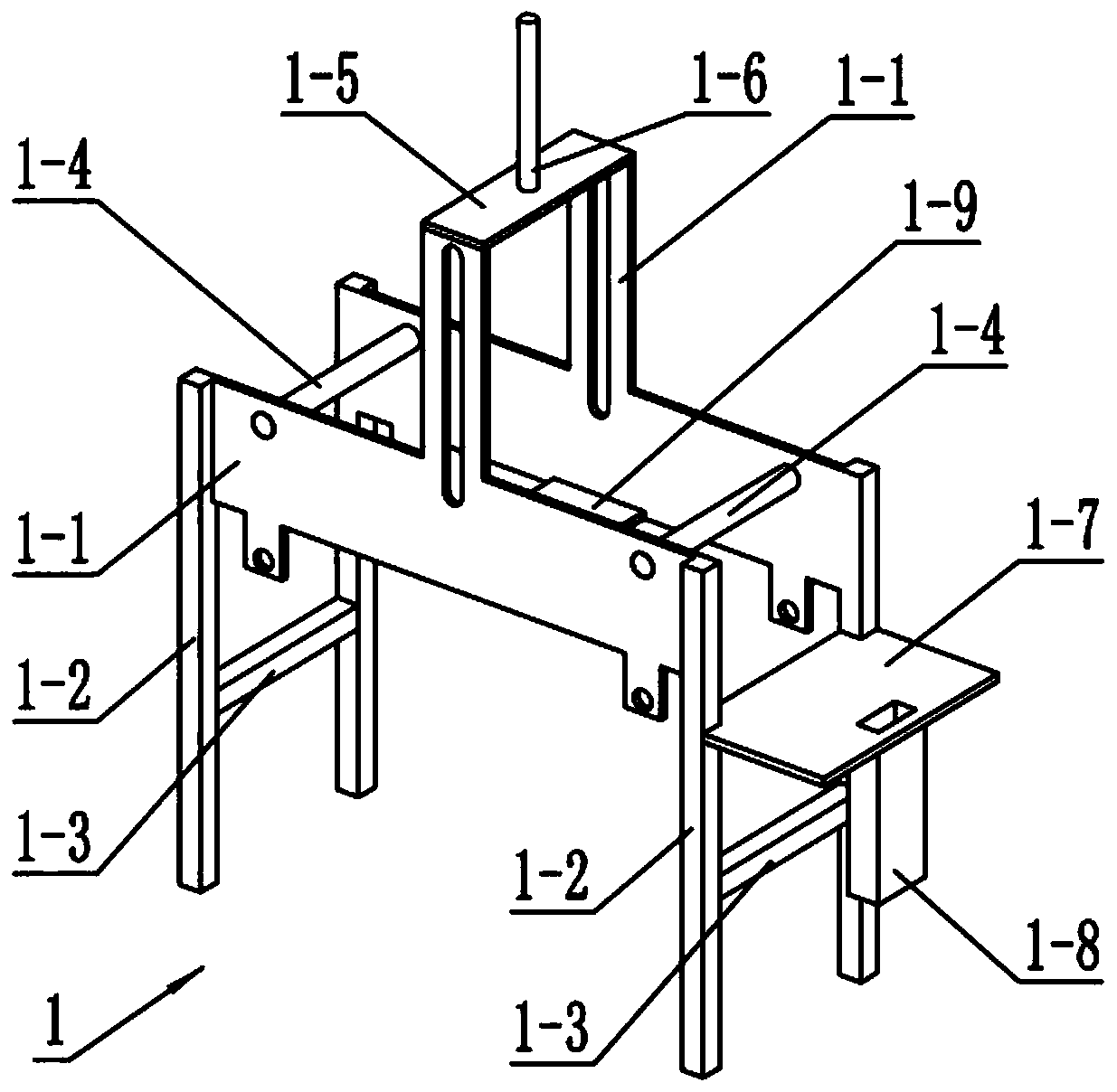
[0033] Such as Figure 1-11 As shown, the bracket 1 includes side plates 1-1, legs 1-2, cross bars 1-3, sliding shafts 1-4, upper cross plates 1-5, threaded rods 1-6, and mounting plates 1- 7. Fix the box tube 1-8 and the connecting plate 1-9. There are two side plates 1-1. Both ends of the two side plates 1-1 are fixedly connected with legs 1-2, two at the left end. A crossbar 1-3 is fixedly connected between the leg 1-2 and the two legs 1-2 at the right end. There are two sliding shafts 1-4, and the two sliding shafts 1-4 are rotatably connected to the two Between the two side plates 1-1, the upper horizontal plate 1-5 is fixedly connected to the upper ends of the two side plates 1-1, the connecting plate 1-9 is fixedly connected to the lower ends of the two side plates 1-1, and the threaded rod 1- 6 is fixedly connected to the upper horizontal plate 1-5, the mounting plate 1-7 is fixedly connected to the two legs 1-2 at the right end, and the fixed box pipe 1-8 is fixedly c...

specific Embodiment approach 3

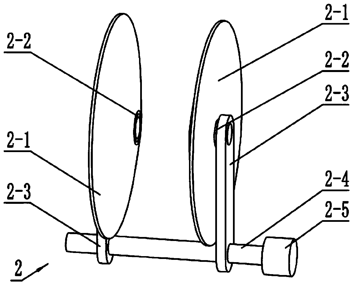
[0036] Such as Figure 1-11 As shown, the guide wheel mechanism 2 includes a tapered side wheel 2-1, a wheel sleeve 2-2, a threaded plate 2-3, a double threaded rod 2-4, and a guide wheel adjustment motor 2-5. The tapered side wheel There are two 2-1, the two tapered side wheels 2-1 are rotatably connected to the wheel sleeve 2-2, the two tapered side wheels 2-1 are arranged oppositely, and the two wheel sleeves 2-2 are both fixed Connected to the threaded plate 2-3, the two threaded plates 2-3 are connected to the two ends of the double-threaded rod 2-4 by threads, the threads of the two ends of the double-threaded rod 2-4 are opposite to each other. The output shaft of the guide wheel adjustment motor 2-5 is fixedly connected, the guide wheel mechanism 2 is provided with two, the two double threaded rods 2-4 are both rotatably connected to the two side plates 1-1, two sets of wheel sets 2-2 They are slidably connected to the two sliding shafts 1-4, and the two guide wheel ad...


PUM


Abstract

The invention relates to the field of machining equipment, in particular to round steel polishing machining device. The round steel polishing machining device comprises a bracket, guide wheel mechanisms, a moving mechanism, an adjusting lifting mechanism, a polishing power rack, a rotating mechanism, an jacking and tightening mechanism, a tensioning mechanism and a polishing mechanism, wherein thetwo guide wheel mechanisms are both connected onto the bracket; the adjusting lifting mechanism is connected to the upper end of the bracket; the moving mechanism is connected onto the adjusting lifting mechanism and is in sliding connection with the bracket; the polishing power rack is connected to the upper end of the bracket; the rotating mechanism is in transmission connection with the polishing power rack; the jacking and tightening mechanism is connected onto the rotating mechanism; the tensioning mechanism is in sliding connection with the rotating mechanism; the polishing mechanism isrotationally connected onto the jacking and tightening mechanism; and the rotating mechanism, the jacking and tightening mechanism, the tensioning mechanism and the polishing mechanism are in transmission connection. The round steel polishing machining device can polish round steel, and the condition that the quality of a workpiece is affected due to the fact that the round steel wobbles with adoption of manual pressing is avoided.

Description

Technical field [0001] The invention relates to the field of mechanical processing equipment, in particular to a round steel polishing processing device. Background technique [0002] In order to remove the oxide or corrosion on the outer surface of the round steel rod, the prior art scheme usually uses a shot blasting machine to perform shot blasting to clean the outer surface of the round steel rod. Although this method can remove the surface oxide or rust, many small pits will be formed on the surface of the workpiece, and the surface roughness will be reduced, which will affect the quality of the product. Nowadays, polishing machines are also used to polish the outer surface of round steel. However, the polishing wheels of the existing polishing machines are manually pressed, which is prone to shaking, which makes the surface of the workpiece form many traces and reduces the surface smoothness of the workpiece. , Affecting the quality of the product. Summary of the inventio...

Claims


Application Information

Patent Timeline
Patent Type & Authority Applications(China)
IPC IPC(8): B24B27/00B24B27/033B24B29/04B24B41/06B24B47/00B24B47/12B24B47/20B24B47/22
CPCB24B27/003B24B27/0069B24B27/033B24B29/04B24B41/067B24B47/00B24B47/12B24B47/20B24B47/22
Inventor 王晓满
Owner 抚州市圣航洁具有限公司
Why Eureka
Try Eureka