Device and method for realizing aircraft flow control based on plasma exciter

A plasma and flow control technology, which is applied in the direction of plasma, aircraft control, and influences the air flow flowing through the surface of the aircraft, to achieve the effects of simple structure, improved lift, and working frequency bandwidth

Active Publication Date: 2020-08-07
NANJING UNIV OF SCI & TECH
View PDF11 Cites 5 Cited by
  • Summary
  • Abstract
  • Description
  • Claims
  • Application Information

AI Technical Summary

Problems solved by technology

However, the existing flow control cannot realize the three-dimensional active flow control of the aircraft well.

Method used


Image

  • Device and method for realizing aircraft flow control based on plasma exciter
  • Device and method for realizing aircraft flow control based on plasma exciter
  • Device and method for realizing aircraft flow control based on plasma exciter

Examples


Embodiment 1

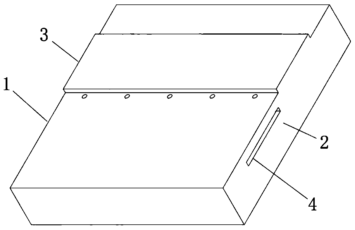
[0033] combine figure 1 , a device for realizing aircraft flow control based on a plasma actuator, comprising a dielectric barrier discharge actuator, a plasma synthetic jet actuator, an insulating medium 1 and a high-voltage power supply, and the dielectric barrier discharge actuator includes a high-voltage electrode block 3 and A ground electrode block 4, the plasma synthetic jet exciter includes an exciter cavity 2, a first electrode rod 5 and a second electrode rod 6, a through hole is provided between the upper and lower surfaces of the insulating medium 1, and the high voltage electrode The block 3 is located on the upper surface of the insulating medium 1 on one side of the through hole, the ground electrode block 4 is located in the insulating medium 1 on the other side of the through hole, and the exciter cavity 2 and the insulating medium 1 The lower surface is connected, the through hole communicates with the exciter cavity 2, the first electrode rod 5 and the secon...

Embodiment 2

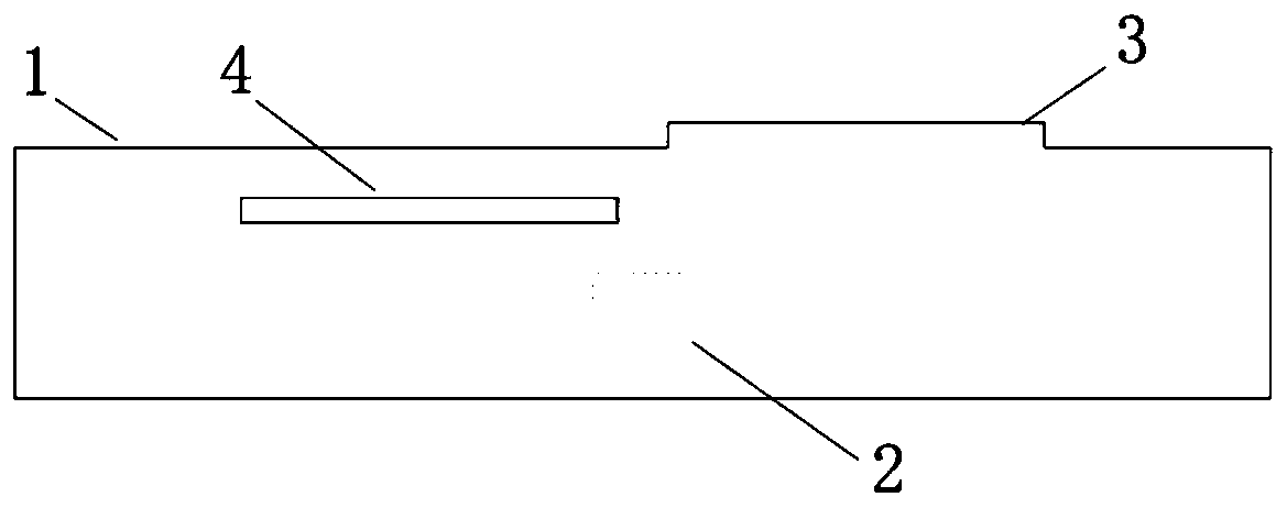
[0035] combine Figure 2-5 , a device for realizing aircraft flow control based on a plasma actuator, comprising a dielectric barrier discharge actuator, at least one plasma synthetic jet actuator, an insulating medium 1 and a high-voltage power supply, the dielectric barrier discharge actuator comprising a high-voltage electrode block 3 and a ground electrode block 4, the plasma synthetic jet exciter includes a first electrode rod 5 and a second electrode rod 6, the upper and lower surfaces of the insulating medium 1 are penetrated by the first hole and the second hole communicated, The high-voltage electrode block 3 is located on the upper surface of the insulating medium 1 on one side of the first hole, the ground electrode block 4 is located in the insulating medium 1 on the other side of the first hole, and the second hole The inner cavity forms the exciter cavity 2, and the first electrode rod 5 and the second electrode rod 6 protrude from the insulating medium 1 into th...


PUM


Abstract

The invention discloses a device and a method for realizing aircraft flow control based on a plasma exciter. The device comprises a dielectric barrier discharge exciter, a plasma synthetic jet exciter, an insulating medium and a high-voltage power supply, the dielectric barrier discharge exciter comprises a high-voltage electrode block and a grounding electrode block; the plasma synthetic jet exciter comprises a first electrode bar and a second electrode bar, the insulating medium is penetrated by the first hole and the second hole, the high-voltage electrode block is located on the upper surface of the insulating medium, the grounding electrode block is located in the insulating medium, an internal cavity of the second hole forms an exciter cavity, and the first electrode bar and the second electrode bar respectively extend into the exciter cavity from the insulating medium. Jet flow generated by the dielectric barrier discharge exciter can be used for controlling separation of a flowfield on the surface of an aircraft, reducing flight resistance and improving lift force; jet flow generated by the plasma synthetic jet flow exciter can be used for changing the flight attitude of the aircraft and providing thrust required by flight.

Description

technical field [0001] The invention belongs to the field of flow control of an external flow field of an aircraft, and in particular relates to a device and method for realizing flow control of an aircraft based on a plasma actuator. Background technique [0002] Nowadays, various aircrafts develop rapidly and are gradually applied in our life. People's requirements for the performance of aircraft are also getting higher and higher, specifically manifested in fast flight speed, drag reduction and noise reduction, energy saving and high efficiency, and maneuverability. Existing aircraft wings are prone to airflow separation when the angle of attack is large, so that the wings lose sufficient lift prematurely, which threatens the safety of the aircraft. The active flow control actuator is essentially an energy conversion device, which realizes the manipulation of the external flow field by converting the input chemical energy, electrical energy, mechanical energy, etc. into ...

Claims


Application Information

Patent Timeline
Patent Type & Authority Applications(China)
IPC IPC(8): B64C23/00H05H1/24
CPCB64C23/005H05H1/2406
Inventor 张小兵李晋峰
Owner NANJING UNIV OF SCI & TECH
Why Eureka
Try Eureka