Quick tensioning device for prestressed anchor rods and construction method

A tensioning device and prestressing technology, applied in infrastructure engineering, construction, sheet pile walls, etc., can solve problems such as different screw pitches, and achieve the effects of avoiding slippage, reducing equipment costs, and high reliability.

Pending Publication Date: 2020-08-07
深圳市东深工程有限公司
View PDF1 Cites 1 Cited by
  • Summary
  • Abstract
  • Description
  • Claims
  • Application Information

AI Technical Summary

Problems solved by technology

[0005] The hydraulic single-cylinder tensioner is connected to the anchor rod through the threaded hole at the bottom of the connecting rod. This connection directly leads to certain limitations of the hydraulic single-cylinder tensioner. A hydraulic single-cylinder tensioner It can only be applied to one specification of anchor rods (the diameter of the rod body of different specifications of the anchor rod is different, and the distance between the threads on the rod body is also different)

Method used


Image

  • Quick tensioning device for prestressed anchor rods and construction method
  • Quick tensioning device for prestressed anchor rods and construction method
  • Quick tensioning device for prestressed anchor rods and construction method

Examples


Embodiment 1

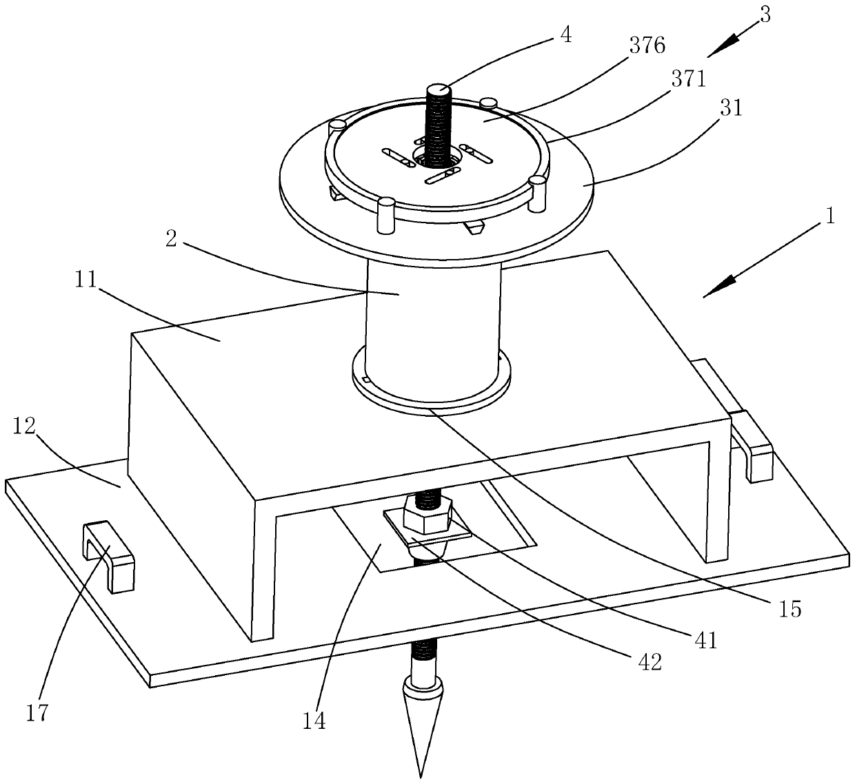
[0045] refer to figure 1 , is a prestressed fast tensioning device for anchor rods disclosed in the present invention, which can perform tension work on anchor rods 4 of different specifications, with relatively small limitations. The prestressed anchor fast tensioning device includes a base 1, a piercing cylinder 2 arranged on the base 1, and a locking mechanism arranged on the top of the piercing cylinder 2 for connecting the piston barrel of the piercing cylinder 2 with the anchor rod 4 3.

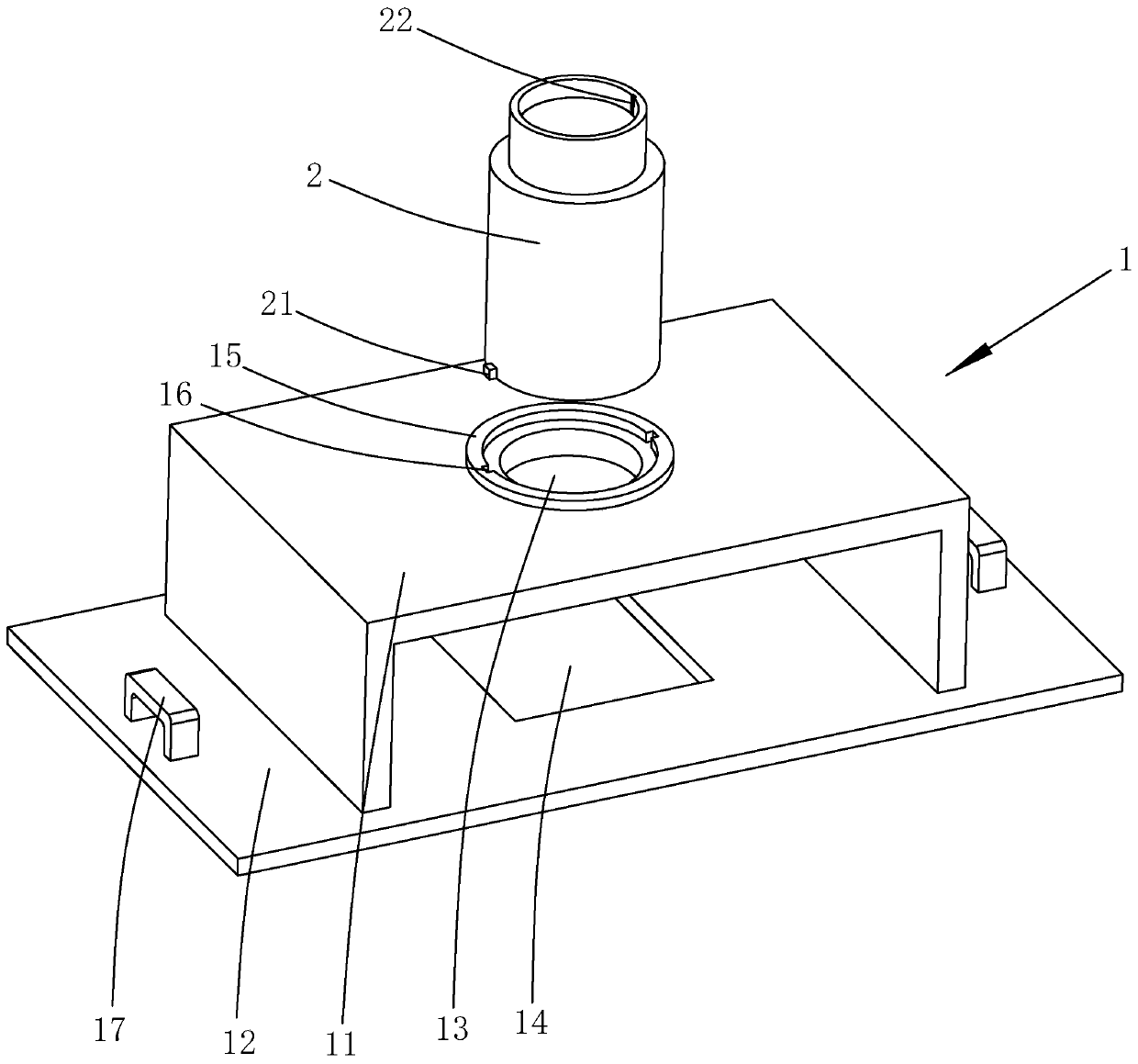
[0046] refer to figure 2, the base 1 includes a base plate 12 and a U-shaped plate 11, the U-shaped plate 11 is buckled upside down in the middle of the upper side of the base plate 12 and the two ends of the U-shaped plate 11 are welded to the base plate 12, and a first through hole is opened at the center of the U-shaped plate 11 13. A second through hole 14 is provided at a position corresponding to the first through hole 13 on the base plate 12, and the first through hole 13 and ...

Embodiment 2

[0055] A fast tensioning method for an anchor rod 4, using the prestressed fast tensioning device for an anchor rod disclosed in Embodiment 1 to perform some steps, the method includes the following steps:

[0056] Step 1. Use a drilling rig to drill holes in the ground;

[0057] Step 2, placing the anchor rod 4: place the anchor rod 4 at the center of the borehole to ensure that the anchor rod 4 is concentric with the borehole, and perform concrete grouting in the borehole;

[0058] Step 3: Apply prestress to the anchor rod 4 after the concrete grouting is solidified: first put the backing plate 42 on the anchor rod 4; then screw the nut 41 onto the backing plate 42; then put the base 1 on the anchor rod 4 Then put the threading oil cylinder 2 on the base 1 and make the anchor rod 4 pass through the threading oil cylinder 2; then open the drive assembly 37 so that the splint 36 hugs the anchor rod 4; then control the threading oil cylinder 2 to extend, to Pull the anchor rod...


PUM


Abstract

The invention relates to a quick tensioning device for prestressed anchor rods and a construction method. The quick tensioning device comprises a base, a center penetrating oil cylinder arranged on the base, a fixing ring detachably connected to the upper end of a piston barrel of the center penetrating oil cylinder, a plurality of guide rails fixed to the upper side of a fixing disc in a radial shape with the piston barrel of the center penetrating oil cylinder as the center, a plurality of sliding blocks connected to the guide rails in a sliding mode and a driving assembly synchronously driving all the sliding blocks to be close to or away from the center penetrating oil cylinder along the guide rails, and clamping plates are fixed to the sides, facing the center penetrating oil cylinder, of the sliding blocks; and an anchor rod passing hole is formed in the middle of the base, and a wrench passing space is formed in the side face of the base. The quick tensioning device has the advantages that the quick tensioning device can be suitable for the anchor rods of different specifications, and the limitation is small.

Description

technical field [0001] The invention relates to the field of tensioning construction of prestressed anchor rods, in particular to a rapid tensioning device and construction method for prestressed anchor rods. Background technique [0002] The prestressed anchor rod is composed of an anchor head, a rod body and a backing plate. The anchoring force generated by the anchor head exerts a certain precompression stress on the surrounding rock and actively strengthens the surrounding rock. [0003] In the process of engineering construction, more and more prestressed anchors are directly prestressed by the tension method. This prestressing method is more accurate and safer than torque wrench. It does not need to measure the torque coefficient, and can realize Multiple times of tensioning and disassembly, suitable for prestressing of anchor rods of various specifications. [0004] The Chinese patent whose publication number is CN106284344B discloses a hydraulic single-cylinder tens...

Claims


Application Information

Patent Timeline
IPC IPC(8): E02D5/74
CPCE02D5/74
Inventor 余奇友傅朝成文建生胡木强
Owner 深圳市东深工程有限公司
Why Eureka
Try Eureka