
Synthetic system and method for sludge soil layer deep foundation pit supporting

A deep foundation pit support and comprehensive system technology, applied in the field of comprehensive system of deep foundation pit support in muddy soil, can solve the problem that horizontal steel support is easy to hinder the construction personnel's operation, the ability to resist horizontal load is limited, and the foundation floor cannot be replaced. problems such as bracing, so as to avoid the safety hazards of the enclosure structure, save the amount of steel, and increase the rigidity and bearing capacity.

Inactive Publication Date: 2020-08-07
CHINA FIRST METALLURGICAL GROUP
View PDF8 Cites 0 Cited by
  • Summary
  • Abstract
  • Description
  • Claims
  • Application Information

AI Technical Summary

Problems solved by technology

However, the horizontal steel support is horizontal in the middle of the deep foundation pit, so that the space in the deep foundation pit is occupied, so that the horizontal steel support easily hinders the construction personnel's operation, making it difficult for the construction personnel to carry out construction operations in the foundation pit. Therefore, there are still room for improvement
Moreover, most bottom plates are equipped with post-casting belts, and the current support replacement scheme cannot normally carry out the support of the foundation floor under the working condition of the bottom plate with post-casting belts due to its limited ability to resist horizontal loads

Method used


Image

  • Synthetic system and method for sludge soil layer deep foundation pit supporting
  • Synthetic system and method for sludge soil layer deep foundation pit supporting
  • Synthetic system and method for sludge soil layer deep foundation pit supporting

Examples


Embodiment Construction

[0028] In order to facilitate those of ordinary skill in the art to understand and implement the present invention, the present invention will be described in further detail below in conjunction with the accompanying drawings and embodiments. It should be understood that the implementation examples described here are only used to illustrate and explain the present invention, and are not intended to limit this invention.

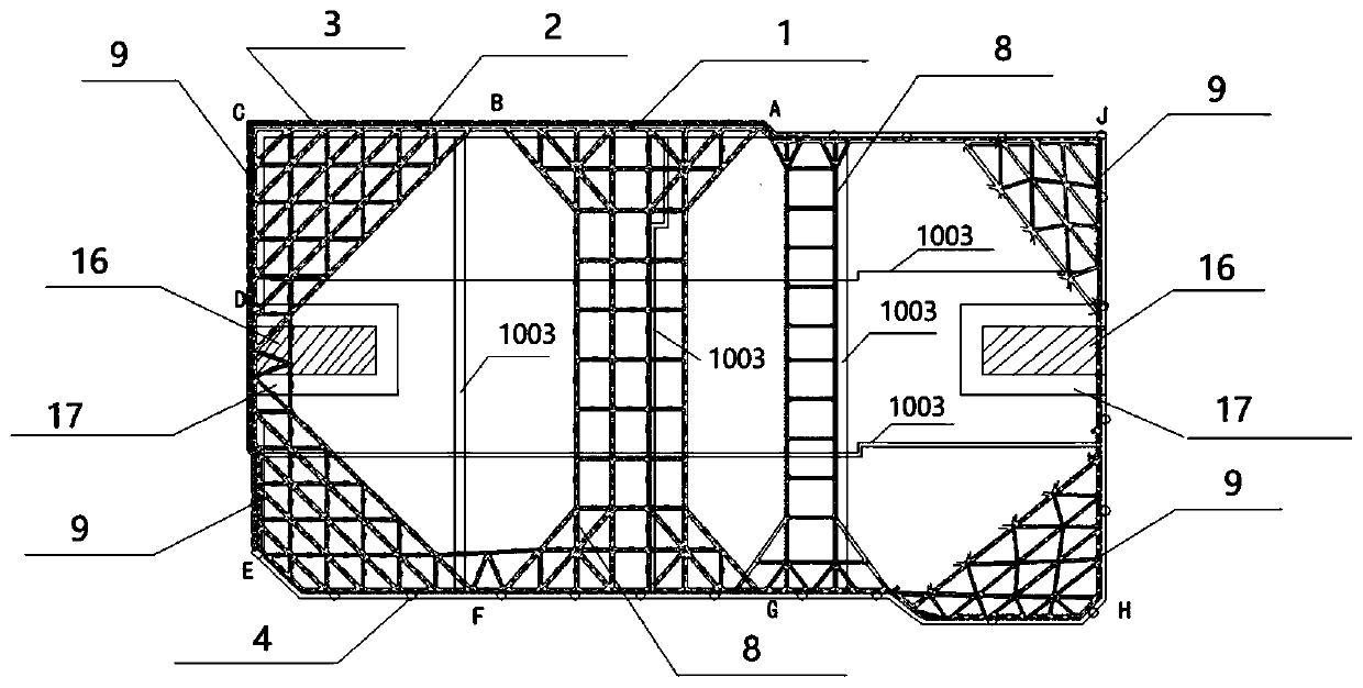
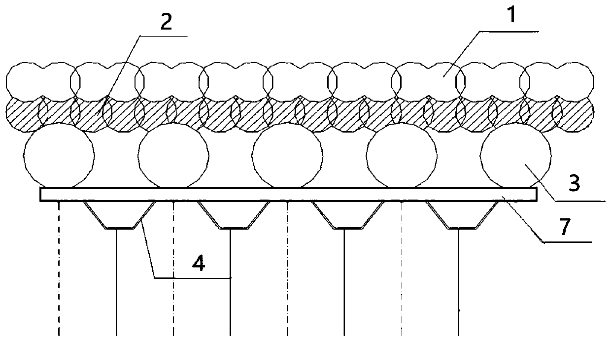
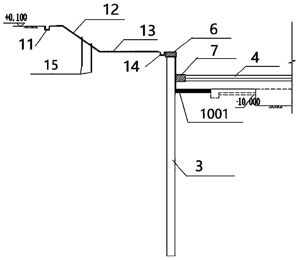
[0029] please see Figure 1-Figure 7 , a comprehensive system for deep foundation pit support in silty soil layer provided by the present invention, including ABCDE silt soil body support area, EFGHJA soft soil body support area, floor layer, ESC-H Larsen pile 4 , Reinforced high-pressure rotary grouting cement-soil pile anchor rod 5, ring-shaped crown beam and waist beam; ABCDE silt soil support area includes biaxial cement mixing pile 1, high-pressure rotary grouting pile 2, punching cast-in-place pile 3; several Biaxial cement mixing piles 1 are arranged ...


PUM


Abstract

The invention discloses a synthetic system and method for sludge soil layer deep foundation pit supporting. The system comprises ABCD sludge soil mass supporting portion regions, EFGHJA soft soil layer supporting portion regions, a bottom plate layer, ESC-H Larsen piles, reinforced high-pressure jet grouting cement soil pile anchor rods, annular crown beams and waist beams. The multiple reinforcedhigh-pressure jet grouting cement soil pile anchor rods are fixedly arranged in soil mass around the wall of a foundation pit. The ABCD sludge soil mass supporting portion regions and the EFGHJA softsoil layer supporting portion regions are connected end to end to form a polygon. The annular crown beams are fixedly arranged on the top of the polygon in the ABCD sludge soil mass supporting portion regions, the annular waist beams are arranged in the middle of an inner cavity, and the bottom plate layer is arranged at the bottom of the inner cavity. The multiple ESC-H Larsen piles are arrangedbetween the annular crown beams. The shortage in traditional steel plate pile application is overcome, the use amount of steel is optimized and reduced, envelop structure potential safety hazards caused by the fact that the rigidity of a supporting plate belt is too high in a weak portion of a water stop envelop structure are avoided, and the synthetic system and method have high cost performancein a deep foundation pit supporting structure.

Description

technical field [0001] The invention belongs to the technical field of deep foundation pit support, and in particular relates to a comprehensive system and method for deep foundation pit support in muddy soil layers. Background technique [0002] With the rapid development of the construction industry, more and more deep foundation pit projects are becoming more and more complicated, and the requirements for safety and construction period are also getting higher and higher. The traditional brace replacement method for deep foundation pit support has a long construction period, and the brace replacement system can easily cause damage to the water stop enclosure structure due to the excessive load transmitted to the water stop enclosure structure, threatening the safety of the foundation pit. In the prior art, multi-layer horizontal steel supports are usually used to support the double-row piles on both sides of the deep foundation pit, thereby improving the stability of the d...

Claims


Application Information

Patent Timeline
IPC IPC(8): E02D17/04E02D5/46E02D5/34E02D5/76E02D5/04E02D19/18
CPCE02D5/04E02D5/34E02D5/46E02D5/76E02D17/04E02D19/18
Inventor 杨志军黄轶赵海莲张帆金坤
Owner CHINA FIRST METALLURGICAL GROUP
Learn More