
Gas pressure measuring device and gas pressure measuring method

A pressure measuring device and gas technology, applied in measurement, earthwork drilling, borehole/well components, etc., can solve problems such as limited sealing and inaccurate gas pressure

Inactive Publication Date: 2020-08-07
HUAINAN MINING IND GRP +3
View PDF10 Cites 2 Cited by
  • Summary
  • Abstract
  • Description
  • Claims
  • Application Information

AI Technical Summary

Problems solved by technology

[0004] However, the tightness between the grouting bag and the piezometer borehole is limited, and the water from the aquifer will enter the coal seam and then enter the piezometric pipe, resulting in inaccurate gas pressure measured by the air pressure detection equipment

Method used


Image

  • Gas pressure measuring device and gas pressure measuring method
  • Gas pressure measuring device and gas pressure measuring method
  • Gas pressure measuring device and gas pressure measuring method

Examples


Embodiment 1

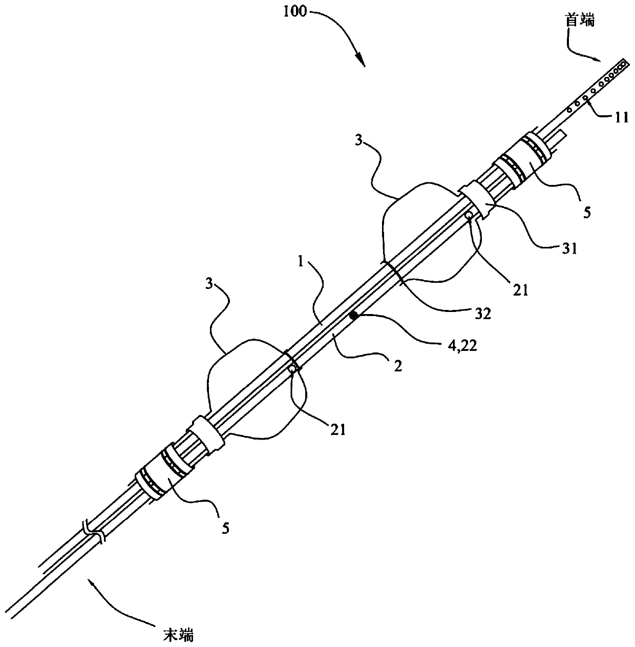
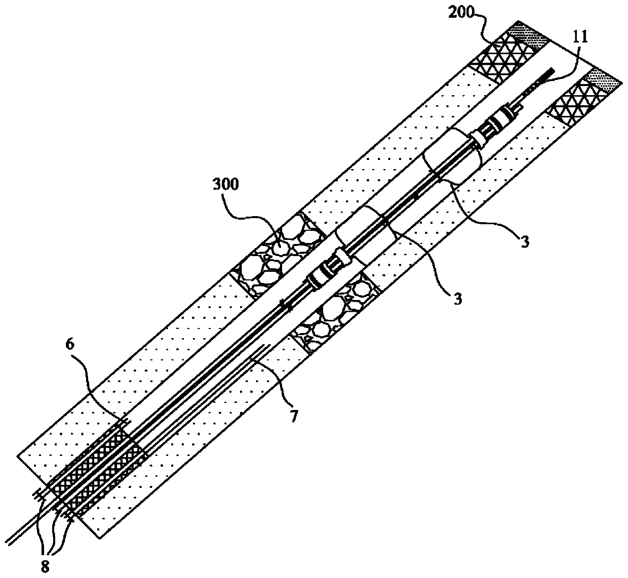
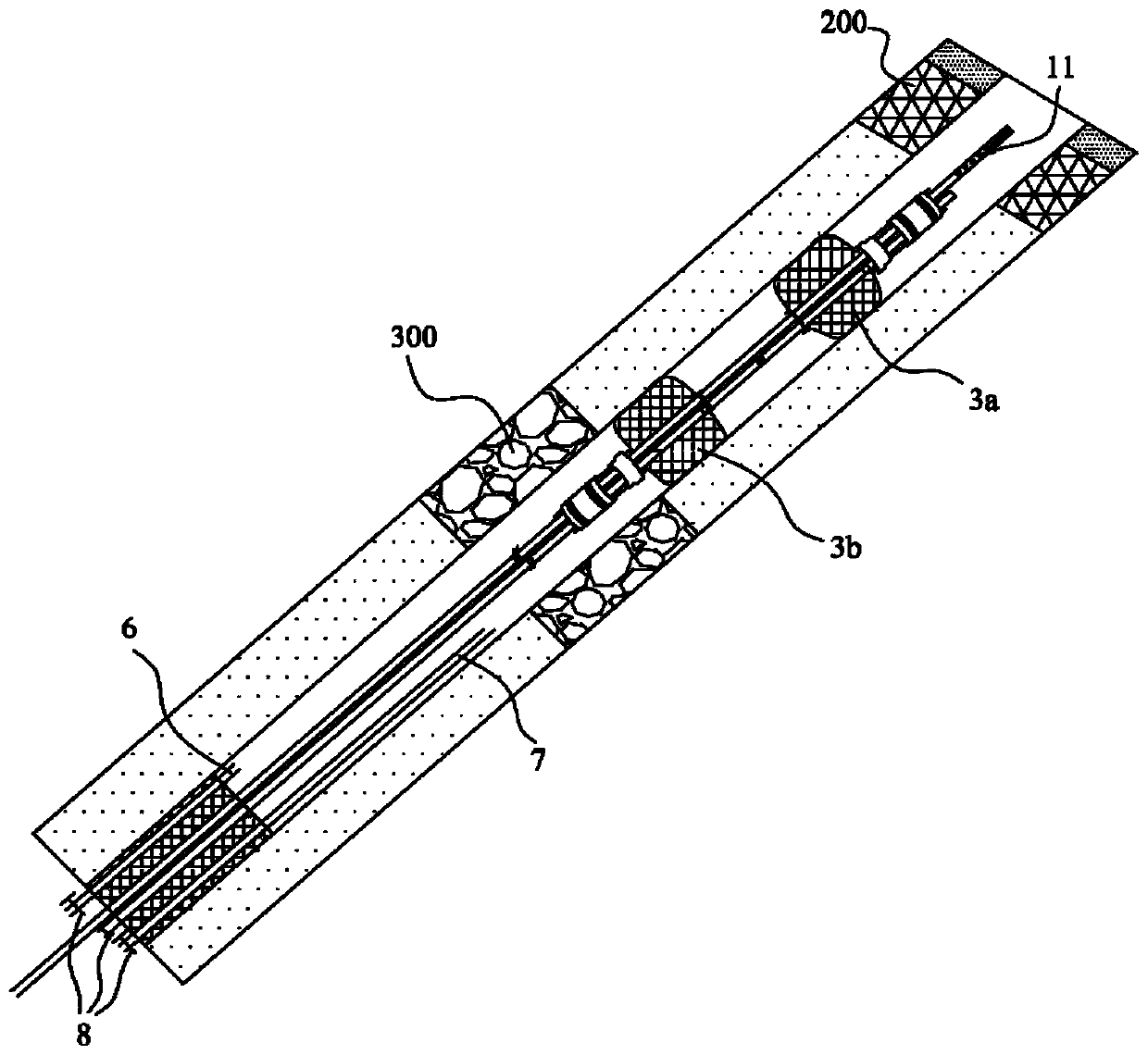
[0059] figure 1 A schematic diagram of a gas pressure measuring device provided in an embodiment of the present invention; figure 2 A schematic diagram of the gas pressure measuring device installed in the pressure measuring borehole provided by the embodiment of the present invention; image 3 A schematic diagram of the gas pressure measuring device provided by the embodiment of the present invention after the first grouting; Figure 4 A schematic diagram of the gas pressure measuring device provided by the embodiment of the present invention after the second grouting; Figure 5 A schematic diagram of the gas pressure measuring device provided by the embodiment of the present invention after the third grouting; Figure 6 A schematic diagram of the gas pressure measuring device provided by the embodiment of the present invention after the fourth grouting; Figure 7 It is a schematic diagram of pressure measurement performed by the gas pressure measurement device provided b...

Embodiment 2

[0083] Figure 8 The flow chart of the gas pressure measurement method provided by the embodiment of the present invention Figure 1 ; Figure 9 The flow chart of the gas pressure measurement method provided by the embodiment of the present invention Figure II .

[0084] Such as Figure 8 As shown, the embodiment of the present invention provides a gas pressure measurement method, including:

[0085] S100. Perform the first grouting through the first grouting pipe and the grouting bag.

[0086] S200. Perform the second grouting through the first grouting pipe and the switching device.

[0087] S300. Obtain the gas pressure through the pressure measuring tube 1.

[0088] Such as Figure 1-7 As shown, in the gas pressure measurement method provided by the embodiment of the present invention, the gas pressure measurement device 100 provided by this embodiment, the first grouting pipe 2 is arranged in parallel with the pressure measurement pipe 1, and the first grouting pi...


PUM


Abstract

The embodiment of the invention provides a gas pressure measuring device and a gas pressure measuring method, and relates to the technical field of gas pressure detection. The gas pressure measuring device comprises a pressure measuring pipe, a first grouting pipe, grouting bags and a switch device, the head end of the pressure measuring pipe is used for extending into a coal seam, the tail end ofthe pressure measuring pipe is connected with an air pressure detecting device; the first grouting pipe is parallel to the pressure measuring pipe, a plurality of first grouting holes are formed in the first grouting pipe at intervals in the center line direction, a second grouting hole is formed between every two adjacent first grouting holes; the grouting bags wrap the pressure measuring pipe and the first grouting pipes, each first grouting hole is communicated with one grouting bag, each grouting bag is used for being arranged between the coal seam and an aquifer; and the switch device blocks the second grouting hole and is used for opening the second grouting hole when the pressure in the first grouting pipes reaches a preset value. According to the gas pressure measuring device andthe gas pressure measuring method, concrete which flows out of the second grouting hole is in direct contact with the side wall of the pressure measuring drill hole, so that the sealing effect is improved.

Description

technical field [0001] The embodiments of the present invention relate to the technical field of gas pressure detection, in particular to a gas pressure measurement device and a gas pressure measurement method. Background technique [0002] In the mining process of coal mines, in order to ensure the safety of mining, it is necessary to detect the gas pressure in the coal seam. [0003] In the related technology, the gas pressure in the coal seam is often detected by a gas pressure measuring device. The gas pressure measuring device includes: a piezometric pipe, a grouting pipe, and a pressure measuring device. The piezometric pipe and the grouting pipe are arranged in parallel and connected together. Two grouting bags are wrapped on the wall of the grouting pipe, and the two grouting bags are arranged at intervals along the center line of the grouting pipe. A pressure measuring device is attached to the end of the pressure measuring tube. When in use, it is necessary to op...

Claims


Application Information

Patent Timeline
IPC IPC(8): E21B47/06E21B33/12E21B33/13
CPCE21B33/12E21B33/13E21B47/06
Inventor 周伟詹绍奇马赞汪峰荣曹道舜彭行球马嘉星
Owner HUAINAN MINING IND GRP
Learn More