
A screw vacuum pump temperature control device

A technology for temperature control devices and vacuum pumps, which is applied to components of pumping devices for elastic fluids, pumps, rotary piston type/swing piston type pump components, etc., which can solve the problems of high difficulty in installation and maintenance, increased costs, Problems such as fast motor rotation frequency, achieve the effect of disassembly and installation speed and stability, fast disassembly and installation speed, and avoid overheating and shutdown

Active Publication Date: 2021-11-16
山东凯恩真空技术有限公司
View PDF7 Cites 1 Cited by
  • Summary
  • Abstract
  • Description
  • Claims
  • Application Information

AI Technical Summary

Problems solved by technology

The screw vacuum pump used in some equipment that requires high-speed production, because of the fast rotation frequency of the motor, the self-cooling system cannot meet the cooling requirements, and the temperature will be too high during operation, which will cause the machine to fail to operate normally. The production efficiency requirements of the equipment will be changed at any time, and the screw vacuum pump that does not need high-speed production will not generate high temperature
[0003] The existing patent No. CN104329257A proposes a screw rotor cooling device for a screw vacuum pump, which directly cools the vacuum pump through the cooling device installed on the screw, but it needs to completely disassemble the screw when assembling or using the screw vacuum pump. Vacuum pumps can only be installed, the difficulty of installation and maintenance is high, and it will seriously affect the start-up time of production equipment, and the structures and shapes of various existing screw vacuum pumps are quite different, so it is impossible to guarantee the use of any type of screw vacuum pump
[0004] The existing patent number CN101660532B proposes a multi-stage dry vacuum pump water cooling system, which uses multiple pipelines to realize circulating water cooling for the vacuum pump, but it has extremely high requirements on the environment, and the vacuum pump is mostly installed inside the equipment when used on the equipment , the connection of water pipes is difficult, and the water cooling system requires the cooperation of multiple systems such as waterways, and the user needs to manually operate the start and stop, which greatly increases the cost

Method used


Image

  • A screw vacuum pump temperature control device
  • A screw vacuum pump temperature control device
  • A screw vacuum pump temperature control device

Examples


Embodiment 1

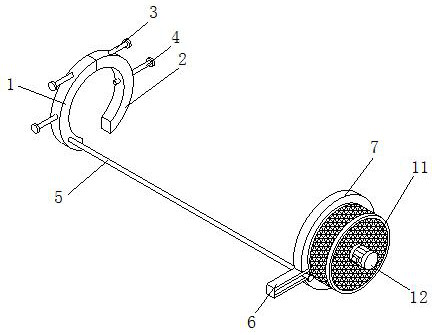
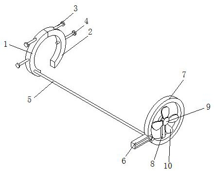
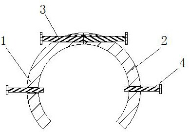
[0043] Example 1: Please refer to Figure 1-4 , a screw-type vacuum pump temperature control device, comprising a left fixed ring 1, a right fixed ring 2 and a cooling ring 7, the left fixed ring 1 and the right fixed ring 2 are fan-shaped, the concave surfaces of the left fixed ring 1 and the right fixed ring 2 Corresponding to left and right, threaded holes are provided on the side tops of the left fixing ring 1 and right fixing ring 2, and the screw threads of the threaded holes on the side tops of the left fixing ring 1 and right fixing ring 2 are opposite in direction, and the left fixing ring 1 and the right fixing ring 2 are on the top sides of the top. The threaded hole of the threaded hole is threadedly connected with the outer walls on both sides of a double-ended screw rod 3. First, the double-ended screw rod 3 is turned to make the distance between the left fixed ring 1 and the right fixed ring 2 longer, and then the space between the left fixed ring 1 and the right...

Embodiment 2

[0045] Embodiment 2: Please refer to the fixed ring 5-8 on the left in the figure. On the basis of Embodiment 1, an annular groove 14 is provided on the back side of the cooling ring 7. The annular groove 14 is an annular groove, and a slider is sleeved in the annular groove 14 B15, the material of the slider B15 is a magnet and is adsorbed in the ring groove 14. The back side of the slider B15 is provided with a word protrusion 16, and the outer wall of the word protrusion 16 is sleeved with a board 17, and the shape of the board 17 is The fan-shaped body, the front of the plug board 17 is provided with a slot 18, the slot 18 is in the shape of a line and is socketed with the protrusion 16 of the line, at first, according to the installation environment of the vacuum pump and the device, a certain number of Slider B15, then on the slider B15, insert the board 17 through the socket of the in-line protrusion 16 and the slot 18, and make the concave surface of the board 17 corres...

Embodiment 3

[0048] Embodiment 3: Please refer to the left fixing ring 9-16 in the figure. On the basis of Embodiment 2, the top surface of the insert plate 17 is provided with mounting holes 41 on both sides of the air outlet 21, and the inner wall of the mounting hole 41 is fixedly connected with Liquid-filled bag 42, liquid-filled bag 42 is a hollow ellipsoid and made of silica gel material, the top surface of cooling ring 7 is fixedly connected with liquid inlet box 22, the top surface of liquid inlet box 22 is hollowed out, and liquid inlet box 22 Sixteen liquid inlet ports 25 are fixedly connected to the back side of the body, and the liquid inlet ports 25 communicate with the inside of the liquid inlet tank 22. The nozzles of the liquid inlet ports 25 are fixedly equipped with pipe covers, and the liquid filling bag 42 is close to one end of the liquid inlet tank 22. The top surface is fixedly connected and communicated with a liquid pipe 27. First, fill the liquid coolant in the liq...


PUM


Abstract

The invention relates to the technical field of screw vacuum pumps, and discloses a screw vacuum pump temperature control device, which includes a left fixed ring, a right fixed ring and a cooling ring. There is a cylindrical protrusion, and the outer wall of the connecting rod is sleeved with a slider A. The shape of the slider A is rectangular and the center of the front is hollowed out. The right side of the slider A is fixedly connected with the cooling ring. Through the setting of the cooling ring, the use The airflow flows from one end of the vacuum pump to the other end, thereby dissipating heat together with the vacuum pump motor and the vacuum pump, avoiding the overheating shutdown of the vacuum pump motor and the overheating and deformation of the vacuum pump, and the synchronous operation of the rotating motor and the vacuum pump to avoid the loss of electrical energy caused by the rotating motor still running after the vacuum pump stops running. The problem of waste can be solved, and the rotation speed of the fan can be changed along with the change of the input voltage of the vacuum pump, so as to automatically adjust the heat dissipation intensity according to the usage of the vacuum pump.

Description

technical field [0001] The invention relates to the technical field of screw vacuum pumps, in particular to a temperature control device for screw vacuum pumps. Background technique [0002] A device that uses a screw to generate, improve, and maintain vacuum in a closed space is called a screw vacuum pump. The screw vacuum pump used in some equipment that requires high-speed production, because of the fast rotation frequency of the motor, the self-cooling system cannot meet the cooling requirements, and the temperature will be too high during operation, which will cause the machine to fail to operate normally. The production efficiency requirements of equipment will be changed at any time, and screw vacuum pumps that do not require high-speed production will not generate high temperatures. [0003] The existing patent No. CN104329257A proposes a screw rotor cooling device for a screw vacuum pump, which directly cools the vacuum pump through the cooling device installed on ...

Claims


Application Information

Patent Timeline
Patent Type & Authority Patents(China)
IPC IPC(8): F04C25/02F04C29/04
CPCF04C25/02F04C29/04F04C29/042
Inventor 赵彬彬臧邦海
Owner 山东凯恩真空技术有限公司
Learn More