
Electro-hydraulic servo valve overlap rapid pneumatic measurement gas circuit and measurement method

An electro-hydraulic servo valve and pneumatic measurement technology, which is applied in the direction of servo motor assembly, fluid pressure actuation system test, fluid pressure actuation device, etc. Uncertain relative position and other problems, to achieve the effect of ensuring accuracy, short measurement time and high degree of automation

Active Publication Date: 2020-08-07
HUAZHONG UNIV OF SCI & TECH
View PDF7 Cites 2 Cited by
  • Summary
  • Abstract
  • Description
  • Claims
  • Application Information

AI Technical Summary

Problems solved by technology

The above two methods need to go through two processes to realize the measurement of the overlapping amount, namely: the first step, find the middle position, and the second step, use a precision flow sensor to measure the overlapping amount; the measurement time is longer
[0004] In addition, in order to improve the measurement accuracy of the overlapping amount, the measurement range of the flow sensor selected for the electro-hydraulic servo valve overlapping amount measuring device disclosed in the above two invention patents should not be too large
However, when the electro-hydraulic servo valve superimposition measurement device fixes the spool valve pair, the relative position of the spool of the spool valve pair and the valve sleeve is uncertain. The flow rate will exceed the measurement range of the flow sensor, and if it is in the over-range state for a long time, the measurement accuracy of the flow sensor will be reduced

Method used


Image

  • Electro-hydraulic servo valve overlap rapid pneumatic measurement gas circuit and measurement method
  • Electro-hydraulic servo valve overlap rapid pneumatic measurement gas circuit and measurement method
  • Electro-hydraulic servo valve overlap rapid pneumatic measurement gas circuit and measurement method

Examples


Embodiment Construction

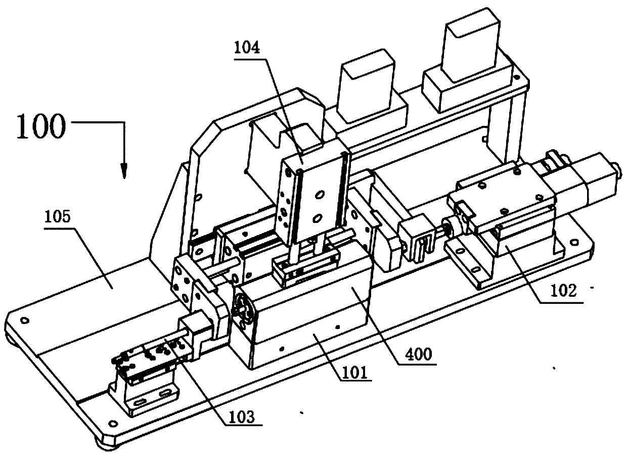
[0045] In order to make the technical means, creative features, goals and effects achieved by the present invention easy to understand, the following will further explain how the present invention is implemented in conjunction with the accompanying drawings and specific implementation methods.

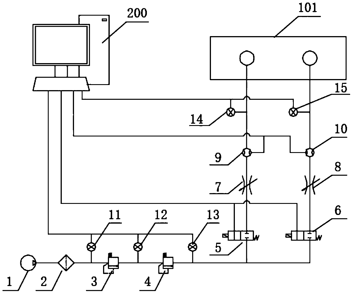
[0046] refer to figure 1 As shown, the present invention provides an electro-hydraulic servo valve fast pneumatic measurement gas path, including a gas source 1, a filter 2, a gas pressure reducing valve 3, a precision pressure reducing valve 4, a first solenoid valve 5, The second solenoid valve 6, the first throttle valve 7, the second throttle valve 8, the first flow sensor 9 and the second flow sensor 10; wherein, the air outlet of the air source 1 communicates with the air inlet of the filter 2, The air outlet of the filter 2 communicates with the air inlet of the gas decompression valve 3, the air outlet of the gas decompression valve 3 communicates with the air inlet of the prec...


PUM


Abstract

The invention discloses an electro-hydraulic servo valve overlap rapid pneumatic measurement gas circuit and a measurement method. The gas circuit is composed of one gas source, one filter, two reducing valves, two solenoid valves, two throttling valves, two flow sensors and a plurality of air pressure sensors; the measurement method comprises the following steps: firstly, acquiring a sample, meeting normal distribution, of an initial position of a valve core of a slide valve pair of an electro-hydraulic servo valve, further obtaining a proper single side confidence interval boundary accordingto the sample and a behavior prediction algorithm, then, before measuring in due form, moving the initial position of the valve core of the slide valve pair to the single side confidence interval boundary firstly, then, starting to control the valve core of the slide valve pair to move left or right, in a process of moving left or right of the valve core, measuring flow rate of a gas circuit through the measurement gas circuit, and feeding back to an industrial personal computer, finally, drawing out full stroke flow rate and displacement curve of the slide valve pair, and obtaining overlap of the slide valve pair through calculation. The gas circuit and the measurement method provided by the invention have the advantages of short measurement process, high test speed, high automation degree, and so on.

Description

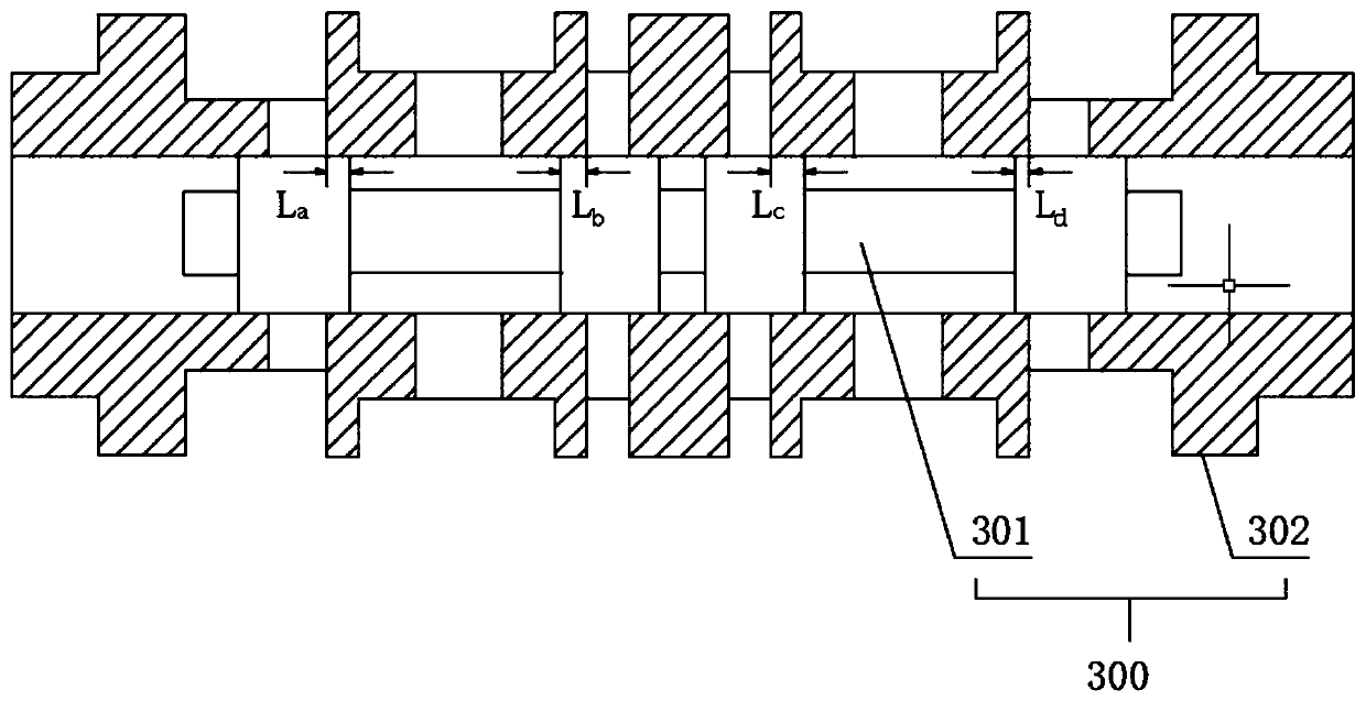
technical field [0001] The present invention relates to the technical field of electro-hydraulic servo valves, in particular to a fast pneumatic measurement gas circuit and measurement method for the stacking amount of an electro-hydraulic servo valve, which is mainly used to cooperate with a measuring device for the stacking amount of an electro-hydraulic servo valve , the stacking amount of the electro-hydraulic servo valve can be measured in one stroke. Background technique [0002] The electro-hydraulic servo valve is an important control element in the electro-hydraulic servo system, and it is mostly used in aerospace, ships, robots and other high-power and high-response occasions. Its manufacturing process requires high precision and is difficult, and the measurement of the stacking amount of the electro-hydraulic servo valve is even more difficult in the manufacturing process. The stacking amount of the electro-hydraulic servo valve refers to the axial matching dimen...

Claims


Application Information

Patent Timeline
IPC IPC(8): F15B19/00F15B13/02F15B21/041
CPCF15B13/02F15B19/00F15B21/041
Inventor 王卓王聃肖力孙志刚
Owner HUAZHONG UNIV OF SCI & TECH
Learn More