LED lamp convenient for heat dissipation

A technology of LED lamps and LED lamp bodies, which is applied to lighting and heating equipment, parts of lighting devices, semiconductor devices of light-emitting elements, etc. Insufficient effect and other problems, to achieve the effect of good construction performance, low shrinkage and high light transmittance

Pending Publication Date: 2020-08-07
湖南正美光电科技有限公司
View PDF0 Cites 0 Cited by
  • Summary
  • Abstract
  • Description
  • Claims
  • Application Information

AI Technical Summary

Problems solved by technology

[0003] However, a large amount of heat will be generated during the lighting process of LED lamps. After the LED lamps are installed, the heat dissipation area is reduced, resulting in poor heat dissipation effect of LED lamps, which directly affects the service life of LED lamps; in order to ensure the cooling effect of LED lamps on the market, Additional ventilation equipment is installed inside the lamp group, which increases the cost of use, occupies a certain amount of use space, and affects the use of users; without ventilation equipment, LED lamps that use ventilation holes to dissipate heat, because they are installed in spaces such as parks and roads, are subject to Under the influence of rain and other factors, water will accumulate inside the LED lamps, which may easily cause safety hazards
[0004] Therefore, the current LED lamps still have insufficient heat dissipation and waterproof performance. Under the premise of ensuring sealing, the heat dissipation effect is greatly reduced; but for the lamp body with some openings for heat dissipation, its waterproof performance is not good. Conducive to the normal operation of internal circuit components

Method used


Image

  • LED lamp convenient for heat dissipation
  • LED lamp convenient for heat dissipation
  • LED lamp convenient for heat dissipation

Examples


Embodiment Construction

[0029] Below in conjunction with accompanying drawing and specific embodiment the present invention is described in further detail:

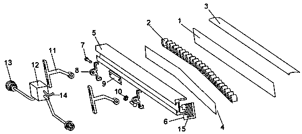
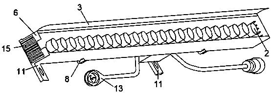
[0030] Such as figure 1 with figure 2 Shown, the technical scheme that the present invention adopts is:

[0031] An LED light fixture for heat dissipation, comprising a fixed assembly, an LED module 2, a heat dissipation module, and a driving power supply. The groove, the fixing groove 4 is set in the groove, and forms a heat dissipation cavity with the groove and the ventilating end cover 6, the LED module 2 is installed on the fixing groove 4, and both sides of the heat dissipation main body 5 are provided with ventilating endcaps 6. The top of the heat dissipation body 5 is covered with a transparent cover plate 1. The air-permeable end cover 6 and the transparent cover plate 1 encapsulate the LED module 2 in the groove of the heat dissipation body 5; There is an anti-glare lens, and the LED module and the anti-glare lens are connected by...


PUM


Abstract

The invention discloses an LED lamp convenient for heat dissipation. The LED lamp comprises an LED module and a heat dissipation module, the heat dissipation module comprises a heat dissipation body,the two sides of the heat dissipation body are each provided with a breathable end cover, a groove is formed in the heat dissipation body, a fixing groove is formed in the groove, and the fixing groove, the groove and the breathable end covers form a heat dissipation cavity; the LED module is composed of a plurality of LED lamp bodies and arranged on the outer surface of the fixing groove. Lensesare arranged on the LED lamp bodies, and the LED lamp bodies are connected with the lenses through waterproof glue. A convection channel which is through left and right is formed among the ventilationcover plate, the fixing groove and the groove of the heat dissipation body, heat can be quickly removed. Meanwhile, the waterproof glue covers the LED lamp body, rainwater is prevented from splashinginto the LED lamp body, the service life of the LED lamp is prolonged, convenience is brought to people, the structure is simple, and the LED lamp is worthy of popularization.

Description

technical field [0001] The patent of the present invention relates to the technical field of LED lamps, in particular to an LED lamp which is convenient for heat dissipation. Background technique [0002] In recent years, LED lamps have been recognized by the society and widely used due to their energy-saving and high-efficiency, high safety and reliability, and long service life. The field has advanced further. [0003] However, a large amount of heat will be generated during the lighting process of LED lamps. After the LED lamps are installed, the heat dissipation area is reduced, resulting in poor heat dissipation effect of LED lamps, which directly affects the service life of LED lamps; in order to ensure the cooling effect of LED lamps on the market, Additional ventilation equipment is installed inside the lamp group, which increases the cost of use, occupies a certain amount of use space, and affects the use of users; without ventilation equipment, LED lamps that use ...

Claims


Application Information

Patent Timeline
Patent Type & Authority Applications(China)
IPC IPC(8): F21K9/20F21V29/83F21V31/04F21V29/50F21V21/14F21Y115/10
CPCF21K9/20F21V21/14F21V29/50F21V29/83F21V31/04F21Y2115/10
Inventor 刘汉平刘林峰
Owner 湖南正美光电科技有限公司
Why Eureka
Try Eureka