
Flame tube, micro-turbojet engine and preparation process of flame tube

A flame cylinder and cylinder technology applied in the field of micro-turbojet engines, which can solve the problems of small number of parts and increase the residence time of gas, and achieve the effects of reducing manufacturing costs, reducing the risk of easy deformation, and increasing residence time

Active Publication Date: 2021-11-09
AECC HUNAN AVIATION POWERPLANT RES INST
View PDF6 Cites 0 Cited by
  • Summary
  • Abstract
  • Description
  • Claims
  • Application Information

AI Technical Summary

Problems solved by technology

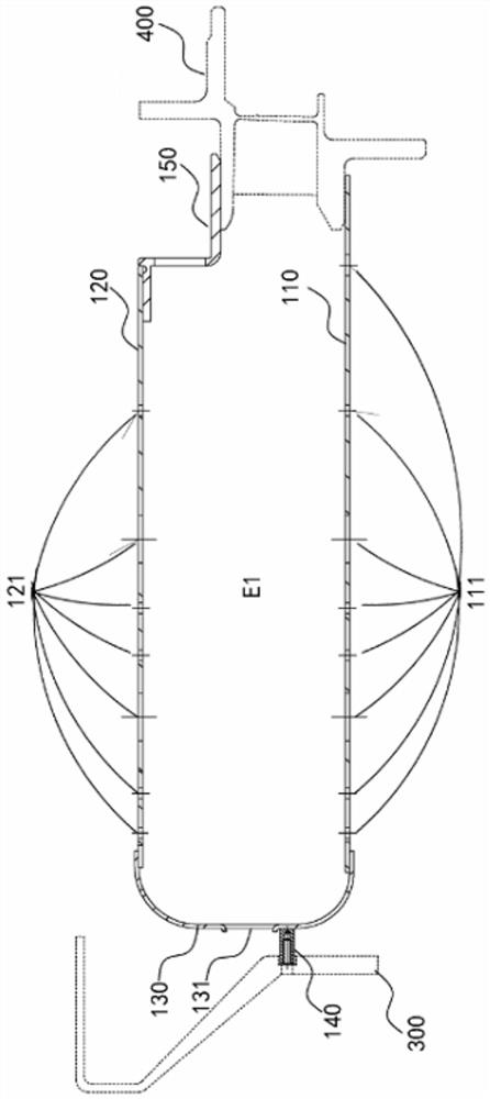
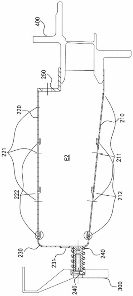
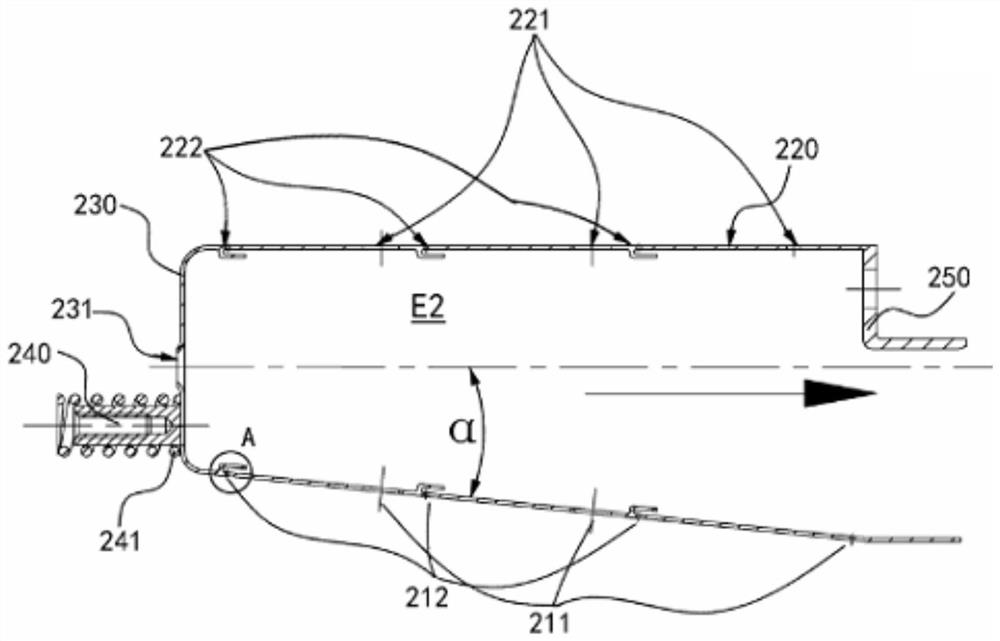
[0005] A main purpose of the present invention is to overcome at least one defect of the above-mentioned prior art, to provide a combustion chamber that can reduce the reference velocity, increase the gas residence time, improve combustion efficiency, have fewer parts, and have a higher degree of integration, which eases the manufacturing process. The flame tube for the problem of deformation of components caused by welding during the process

Method used


Image

  • Flame tube, micro-turbojet engine and preparation process of flame tube
  • Flame tube, micro-turbojet engine and preparation process of flame tube
  • Flame tube, micro-turbojet engine and preparation process of flame tube

Examples


Embodiment Construction

[0061] Typical embodiments embodying the features and advantages of the present invention will be described in detail in the following description. It should be understood that the present invention can have various changes in different embodiments without departing from the scope of the present invention, and that the description and drawings therein are illustrative in nature and not intended to limit the present invention. invention.

[0062] In the following description of various exemplary embodiments of the invention, reference is made to the accompanying drawings, which form a part hereof, and in which are shown by way of example different exemplary structures, systems, and embodiments in which aspects of the invention may be implemented and steps. It is to be understood that other specific arrangements of components, structures, exemplary devices, systems and steps may be utilized and structural and functional modifications may be made without departing from the scope...


PUM


Abstract

The invention proposes a flame cylinder, a micro-turbojet engine and a preparation process for the flame cylinder. The cylinder body of the flame cylinder includes an inner ring wall and an outer ring wall. There is a gas flow channel between the inner ring wall and the outer ring wall. The inner ring wall There is a head between the front end of the head and the front end of the outer ring wall, the front end of the head is connected to a diffuser via a support rod, the rear end of the outer ring wall is provided with a support structure, the rear end of the support structure and the inner ring wall The rear end is connected to a gas turbine guide. Wherein, the inner ring wall, the outer ring wall, the head, the supporting rod and the supporting structure are integrated. The distance between the inner ring wall and the outer ring wall on the same side gradually increases from front to rear in the axial direction, so that the cross-sectional width of the gas flow channel gradually increases from front to rear.

Description

technical field [0001] The invention relates to the technical field of micro-turbojet engines, in particular to a flame cylinder, a micro-turbojet engine and a preparation process for the flame cylinder. Background technique [0002] Micro-turbine engine has the characteristics of small size, light weight, simple structure, low cost, easy maintenance and use, etc. As one of the key components of the micro-turbojet engine, the combustion chamber has the characteristics of small characteristic size, large surface-to-volume ratio, and large flow resistance compared with conventional size combustion chambers. The annular direct-flow combustion chamber of the evaporation tube has a simple structure and low manufacturing cost , Low oil supply pressure and other advantages, it is widely used in micro turbojet engines at present. The flame cylinder is an important part of the combustion chamber. For the micro turbojet engine, the flame cylinder must meet the requirements of simple ...

Claims


Application Information

Patent Timeline
Patent Type & Authority Patents(China)
IPC IPC(8): F23R3/50F02C3/14
CPCF02C3/14F23R3/50
Inventor 王梅娟黄伟王启道丁国玉陈智莹汪玉明
Owner AECC HUNAN AVIATION POWERPLANT RES INST
Learn More