
Cold water air conditioning unit

A technology for air-conditioning units and cold water, which is used in air-conditioning systems, mechanical equipment, space heating and ventilation, etc. It can solve the problems of easy failure of components and slow start-up speed, improve control accuracy and accuracy, reduce heating time, The effect of improving detection stability

Pending Publication Date: 2020-08-07
QINGDAO HAIER AIR CONDITIONING ELECTRONICS CO LTD +1
View PDF6 Cites 1 Cited by
  • Summary
  • Abstract
  • Description
  • Claims
  • Application Information

AI Technical Summary

Problems solved by technology

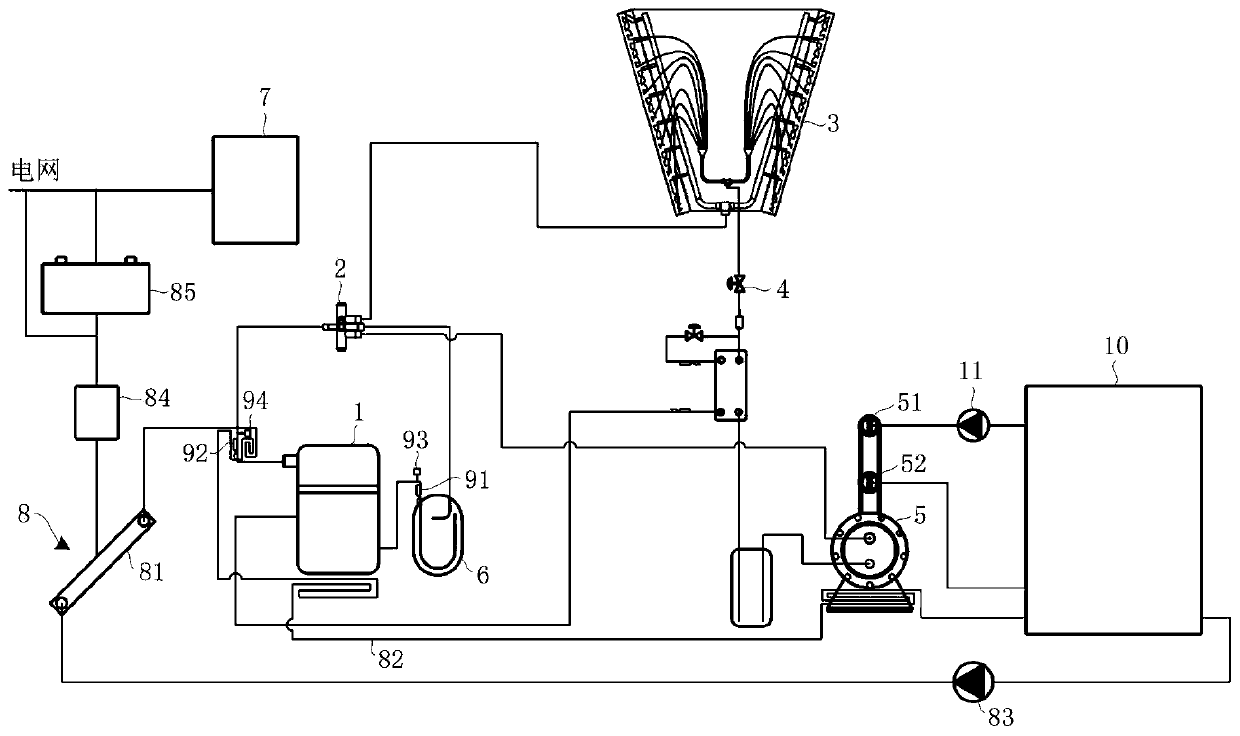
[0005] In order to solve the above-mentioned problems in the prior art, that is, in order to solve the problems of slow start-up speed and easy failure of components of existing chilled water air-conditioning units in low-temperature environments, the present invention provides a chilled water air-conditioning unit, including a compressor connected through a refrigerant pipe. machine, condenser, throttling device, evaporator and multiple electronic components, the chilled water air conditioner unit also includes a solar device, the solar device includes a solar heat collector, a heat pipe and a first circulation pump, and the solar collector The heat collector has a heat collection inlet and a heat collection outlet, and the heat conduction pipes communicate with the heat collection inlet and the heat collection outlet respectively, the first circulation pump is arranged on the heat conduction pipes, and the heat conduction pipes are filled with A heat-conducting medium, and the heat-conducting pipe is partially coiled on the outer bottom of the compressor, the outer bottom of the evaporator or the inside of the evaporator, and around some of the electronic components

Method used


Image

  • Cold water air conditioning unit

Examples


Embodiment Construction

[0024] Preferred embodiments of the present invention are described below with reference to the accompanying drawings. Those skilled in the art should understand that these embodiments are only used to explain the technical principles of the present invention, and are not intended to limit the protection scope of the present invention. For example, although this embodiment is introduced in conjunction with an air-cooled chilled water air conditioner unit, this is not intended to limit the protection scope of the present invention. Those skilled in the art can apply the present invention to Other application scenarios. For example, the present application can also be applied to water-cooled chilled water air-conditioning units and the like.

[0025] It should be noted that, in the description of the present invention, the terms "center", "upper", "lower", "left", "right", "vertical", "horizontal", "inner", "outer" etc. The terms of the indicated direction or positional relati...


PUM


Abstract

The invention relates to the technical field of air conditioning, in particular to a cold water air conditioning unit. The cold water air conditioning unit aims to solve the problems that an existingcold water air conditioning unit is low in starting speed in a low-temperature environment, and components are prone to failure. The cold water air conditioning unit comprises a compressor, a condenser, a throttling device, an evaporator, a plurality of electronic components and a solar device, wherein the solar device comprises a solar heat collector, a heat conduction pipe and a first circulating pump, the solar heat collector is provided with a heat collection inlet and a heat collection outlet, the heat conduction pipe communicates with the heat collection inlet and the heat collection outlet, the first circulating pump is arranged on the heat conduction pipe, the heat conduction pipe is filled with heat conduction media, and part of the heat conduction pipe is arranged at the bottom of the outer side of the compressor, the bottom of the outer side of the evaporator or the interior of the evaporator and on the peripheries of part of the electronic components in a coiled mode. According to the cold water air conditioning unit, the starting speed and the operation efficiency of the cold water air conditioning unit can be greatly improved, and the detection stability of electroniccomponents and the control precision of the unit are improved.

Description

technical field [0001] The invention relates to the technical field of air conditioning, in particular to a cold water air conditioning unit. Background technique [0002] Chilled water air-conditioning units are widely used in various industries. Chilled water air-conditioning units are referred to as chillers, which mainly include compressors, evaporators, condensers, expansion valves, and evaporators usually use shell-and-tube evaporators or sleeve-pipe evaporators. The condenser usually adopts a water-cooled condenser or an air-cooled condenser. During operation, the refrigerant in the evaporator exchanges heat with the brine, and the refrigerant in the condenser exchanges heat with cooling water or outdoor air. [0003] When the unit is shut down in winter, in order to prevent the refrigerant in the evaporator from freezing and damaging the evaporator, it is usually necessary to drain the water in the evaporator. However, when the unit starts running again, it takes a...

Claims


Application Information

Patent Timeline
Patent Type & Authority Applications(China)
IPC IPC(8): F24F5/00F24F11/89F24F13/30
CPCF24F5/001F24F5/0017F24F5/0046F24F11/89F24F13/30F24F2005/0067Y02E60/14
Inventor 王雷孙辉赵雷
Owner QINGDAO HAIER AIR CONDITIONING ELECTRONICS CO LTD
Learn More