Supercharge Your Innovation With Domain-Expert AI Agents!

Calibration method for relative position of linear laser three-dimensional measurement sensor and robot

A technology of three-dimensional measurement and calibration method, applied in the direction of measuring devices, optical devices, instruments, etc., can solve the problem of unable to solve the problem of three-dimensional point cloud coordinate system and camera position calibration, difficult operation of sensor position calibration, and low calibration accuracy (error, etc. problems, to achieve the effect of convenient implementation, reduced complexity, and high precision

Active Publication Date: 2020-08-07
无锡中车时代智能装备研究院有限公司
View PDF8 Cites 8 Cited by
  • Summary
  • Abstract
  • Description
  • Claims
  • Application Information

AI Technical Summary

Problems solved by technology

Among them, the fixed point (standard ball center) pose change method requires the line laser three-dimensional measurement sensor to accurately scan the surface of the standard ball each time, and determine the position of the center coordinates in the measurement coordinate system. For line laser three-dimensional measurement with a small measurement range Measuring the sensor, it is difficult for the robot to achieve multiple pose measurement standard ball center coordinates under the condition of large difference in attitude, which makes the calibration operation of the sensor position with a small measurement range difficult and the calibration accuracy is low (the error is about 1.5mm); the calibration board The position and attitude method requires that the line laser 3D measurement sensor allows users to collect 2D images, and the 3D point cloud coordinate system of the sensor coincides with the coordinate system of the camera, so that the position calibration of the sensor can be accurately realized. This method has limited use scenarios and cannot solve the problem of sensor The position calibration problem of the 3D point cloud coordinate system and the camera coordinate system do not coincide

Method used


Image

  • Calibration method for relative position of linear laser three-dimensional measurement sensor and robot
  • Calibration method for relative position of linear laser three-dimensional measurement sensor and robot
  • Calibration method for relative position of linear laser three-dimensional measurement sensor and robot

Examples


Embodiment Construction

[0029] The present invention will be further described below in conjunction with specific drawings and embodiments.

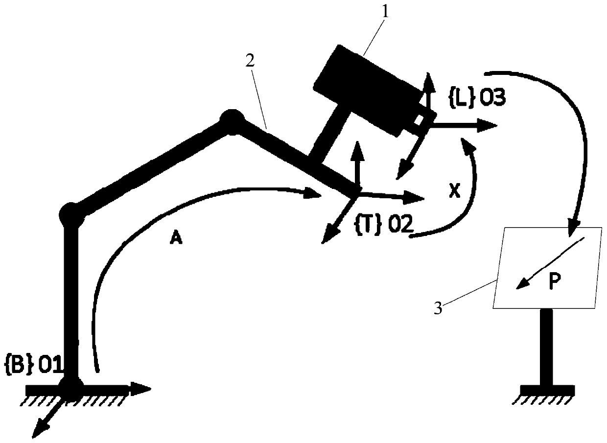
[0030] The embodiment of the present invention proposes a method for calibrating the relative position of the line laser three-dimensional measurement sensor and the robot. In this method, the line laser three-dimensional measurement sensor scans different positions of the standard plane to obtain three-dimensional point cloud data, and the linear equation is fitted to calculate the direction vector of the line. The optimization problem under the constrained plane is used to solve the relative positional relationship between the line laser three-dimensional measurement sensor and the robot, so as to realize the fast and high-precision calibration of the line laser three-dimensional measurement sensor. The method specifically includes:

[0031] The line laser three-dimensional measurement sensor 1 is installed at the end of the robot arm 2; the robot base coordi...


PUM


Abstract

The invention provides a calibration method for the relative position of a linear laser three-dimensional measurement sensor and a robot. According to the method, a line laser three-dimensional measurement sensor scans different positions of a standard plane to obtain three-dimensional point cloud data, a linear equation is fitted to calculate a direction vector of a straight line, and an optimization problem under plane constraint is constructed to calculate a relative position relationship between the line laser three-dimensional measurement sensor and a robot. The calibration operation is simple, and the precision is high, thereby achieving the quick and high-precision calibration of the line laser three-dimensional measurement sensor.

Description

technical field [0001] The invention relates to a position calibration method, in particular to a calibration method for the relative position of a line laser three-dimensional measurement sensor and a robot. Background technique [0002] The line laser three-dimensional measurement sensor is a three-dimensional point cloud measurement sensor using triangulation. It has the advantages of high measurement accuracy, fast speed, and non-contact measurement. It is widely used in three-dimensional measurement, reverse engineering, robot processing and other fields. Since the line laser three-dimensional measurement sensor can only obtain the three-dimensional point cloud coordinates on one laser, in order to realize the overall measurement, it is necessary to use other high-precision measurement platforms to form a measurement system for the overall measurement of the object. The multi-axis industrial robot has the advantages of high position accuracy and simple operation, making...

Claims


Application Information

Patent Timeline
IPC IPC(8): G01B11/00
CPCG01B11/002
Inventor 严思杰吴龙岳晶陈巍李成胡旭
Owner 无锡中车时代智能装备研究院有限公司
Features
  • R&D
  • Intellectual Property
  • Life Sciences
  • Materials
  • Tech Scout
  • Unparalleled Data Quality
  • Higher Quality Content
  • 60% Fewer Hallucinations
Learn More