
Automatic winding machine for high-voltage coil of power transformer

An automatic winding machine, power transformer technology, applied in the direction of inductance/transformer/magnet manufacturing, circuit, coil manufacturing, etc., can solve winding, and has limited or no opportunity to change the thickness, it is difficult to meet the winding requirements of transformer high-voltage wire wrapping, production problems such as low efficiency, to achieve the effect of improving product quality, improving product quality, and saving production costs

Pending Publication Date: 2020-08-07
江苏创凌非晶科技发展有限公司
View PDF0 Cites 1 Cited by
  • Summary
  • Abstract
  • Description
  • Claims
  • Application Information

AI Technical Summary

Problems solved by technology

In traditional winding machines, interlayer insulation is applied manually between layers, usually one or two layers of paper, and the insulating paper is usually the entire width of the coil, in this traditional method the paper is not under tension Winding, and there is limited or no opportunity to change the thickness of the interlayer insulation layer passing through this layer, it is difficult to meet the winding requirements of the existing transformer high-voltage wire package, affect the quality of the product, and the production cost is high and the production efficiency is low

Method used


Image

  • Automatic winding machine for high-voltage coil of power transformer
  • Automatic winding machine for high-voltage coil of power transformer
  • Automatic winding machine for high-voltage coil of power transformer

Examples


Embodiment Construction

[0052] The following will clearly and completely describe the technical solutions in the embodiments of the present invention with reference to the accompanying drawings in the embodiments of the present invention. Obviously, the described embodiments are only some, not all, embodiments of the present invention.

[0053] In describing the present invention, it should be understood that the terms "middle", "upper", "lower", "front", "rear", "left", "right", "vertical", "horizontal", The orientations or positional relationships indicated by "top", "bottom", "inner", "outer", etc. are based on the orientations or positional relationships shown in the drawings, and are only for the convenience of describing the present invention and simplifying the description, rather than indicating or implying the It should not be construed as limiting the invention that a device or element must have a particular orientation, be constructed, and operate in a particular orientation.

[0054] In t...


PUM


Abstract

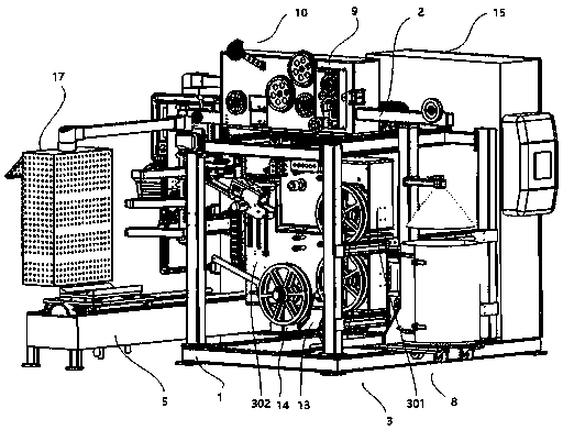
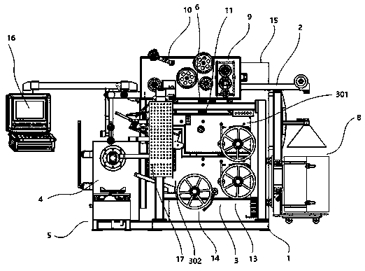
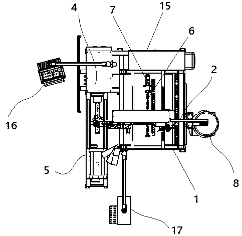
The invention discloses an automatic winding machine for a high-voltage coil of a power transformer. The automatic winding machine comprises a main rack, an electromagnetic wire pay-off rack, an insulation paper pay-off rack, a coil winding device, a coil unloading device and a control system, the electromagnetic wire pay-off rack is installed above the main rack. A first ball screw transmission mechanism is connected with the main rack in a front-back sliding manner; the first ball screw transmission mechanism is connected with a first servo motor; a round wire pay-off device, an electromagnetic wire flattening device and a constant-tension wire arranging device are arranged on the electromagnetic wire pay-off rack; the insulation paper discharging rack is located below the constant-tension wire arranging device and connected with the main rack in a front-back sliding mode through a second ball screw transmission mechanism, the second ball screw transmission mechanism is connected with a second servo motor, and an interlayer insulation discharging device and an end insulation feeding device are arranged on the insulation paper discharging rack. Product quality can be improved, production time is shortened, production cost is saved, and production efficiency of winding the transformer high-voltage wire package is improved.

Description

technical field [0001] The invention belongs to the technical field of production of high-voltage wire packs for power transformers, and in particular relates to an automatic winding machine for high-voltage wire packs for power transformers. Background technique [0002] Automatic intelligent winding machine, manufacturing high voltage wire packs for power transformers, in the construction of liquid filled distribution transformer coils, the coils are usually wound in layers. That is to say, the enamel package is wound in layers, and insulating paper is wound between these layers as interlayer insulation. Specifically, in the high-voltage windings of distribution transformer coils, the conductors are usually smaller cross-section aluminum or copper wires with interlayer insulating paper wound between the wire layers. In traditional winding machines, interlayer insulation is applied manually between layers, usually one or two layers of paper, and the insulating paper is usu...

Claims


Application Information

Patent Timeline
IPC IPC(8): H01F41/063H01F41/094H01F41/096H01F41/098H01F41/12
CPCH01F41/063H01F41/096H01F41/094H01F41/098H01F41/122H01F41/125
Inventor 李明陈中鹤陈政
Owner 江苏创凌非晶科技发展有限公司
Learn More