Multifunctional temperature control heating system

A heating system and multi-functional technology, which is applied in the direction of controlling mechanical energy, magnetic circuit shape/style/structure, magnetic circuit rotating parts, etc., can solve the problem that the high temperature of the permanent magnet cannot be eliminated, the speed of the wind wheel shaft cannot be reduced, and the rotor that generates electrons The shaft speed cannot be reduced, etc.

Inactive Publication Date: 2021-09-14
CHONGQING THREE GORGES UNIV
View PDF6 Cites 0 Cited by
  • Summary
  • Abstract
  • Description
  • Claims
  • Application Information

AI Technical Summary

Problems solved by technology

[0005] The present invention intends to provide a multi-functional temperature-controlled heating system to solve the problem in the prior art that due to the uncontrollable natural wind force, the rotational speed of the wind wheel shaft driven by the wind force cannot be reduced, and the rotational speed of the rotor shaft of the generator cannot be reduced, resulting in permanent The problem that the high temperature phenomenon of the magnet cannot be eliminated

Method used


Image

  • Multifunctional temperature control heating system
  • Multifunctional temperature control heating system

Examples


Embodiment 1

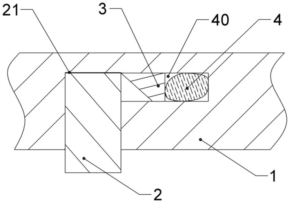
[0024] It is basically shown as follows: a multifunctional temperature-controlled heating system, including a casing and a generator for driving the blades to rotate, the generator is located in the casing, the generator includes a stator and a rotor, and the rotor is provided with a plurality of permanent rotors along the circumferential direction of the rotor yoke 1. Magnet 2; vents are opened on the casing.

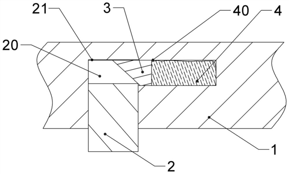
[0025] like figure 1 As shown, the inner wall of the rotor yoke 1 is provided with a sliding groove 20, and the opening of the sliding groove 20 faces the inside of the rotor yoke 1 ( figure 1 The lower part of the rotor yoke 1 is defined as the inside of the rotor yoke 1), and the bottom of the sliding groove 20 is provided with a buffer pad 21 .

[0026] The permanent magnet 2 is slidably connected with the sliding groove 20. Preferably, in order to ensure that the permanent magnet 2 can slide smoothly in the sliding groove 20, lubricating oil is added in the slidin...

Embodiment 2

[0042] The difference from Embodiment 1 is that the driving structure includes a telescopic shaped part for placing the driving part 4, and the telescopic shaped part matches the shape of the driving part 4. In this embodiment, the telescopic shaped part is a rubber airbag. In this embodiment, by setting the telescopic shaping member, the restricting member 3 will gather as much as possible after liquefaction, thereby shortening the length of the driving member 4 and ensuring that the restricting member 3 can return to the original position.


PUM


Abstract

The invention relates to the technical field of temperature control of wind power generators. In order to solve the problem in the prior art that the rotation speed of the rotor shaft of the generator cannot be reduced due to the uncontrollable natural wind force, the high temperature phenomenon of the permanent magnet cannot be eliminated; a multi- The functional temperature-controlled heating system includes a casing and a generator for driving the blades to rotate. The generator includes a rotor and a plurality of permanent magnets; a sliding groove is arranged on the inner wall of the rotor yoke, and the opening of the sliding groove is set toward the inside of the rotor yoke; the permanent magnet It is slidingly connected with the sliding groove, and the side wall at the bottom of the sliding groove is provided with a driving structure. The limiting piece enters into the sliding groove and pushes the permanent magnet to slide toward the inside of the rotor yoke, and the limiting piece returns to the connecting groove after the temperature of the rotor yoke is lowered. The invention can reduce the probability of demagnetization of the permanent magnet.

Description

technical field [0001] The invention relates to the technical field of wind power generator temperature control, in particular to a multifunctional temperature-controlled heating system. Background technique [0002] One of the more readily available clean energy sources is wind power, which converts wind energy into electricity. When working, the wind wheel rotates under the action of wind force, which converts the kinetic energy of the wind into the mechanical energy of the wind wheel shaft. After the wind wheel shaft rotates, the gear transmission structure drives the generator to rotate and generate electricity. In order to reduce the impact of the surrounding environment on wind power, wind turbines are usually set up in open fields, where there are few buildings in the surrounding environment, and the generator is still at a high altitude, so the wind will not weaken due to the influence of buildings. Phenomenon. In this way, when the weather is cold, the temperature...

Claims


Application Information

Patent Timeline
Patent Type & Authority Patents(China)
IPC IPC(8): H02K1/27H02K7/18H02K11/25H02K5/24
CPCH02K1/2786H02K5/24H02K7/183H02K11/25
Inventor 刘利利温玉锋陈才许刚姜友嫦
Owner CHONGQING THREE GORGES UNIV
Why Eureka
Try Eureka