Rotating machine lubrication structure

A technology of rotating machinery and structure, applied in the field of lubricating structure of rotating machinery, it can solve the problems of limited amount of lubricating oil, scattering of lubricating oil, etc., and achieve the effect of efficient lubrication

Active Publication Date: 2020-08-07
TOYOTA JIDOSHA KK
View PDF7 Cites 0 Cited by
  • Summary
  • Abstract
  • Description
  • Claims
  • Application Information

AI Technical Summary

Problems solved by technology

Although there is a gap (gap) between the resolver stator and the resolver rotor, since the resolver rotor rotates integrally with the shaft, the lubricating oil is easily scattered due to centrifugal force, and the amount of lubricating oil supplied to the bearing from this gap is limited.

Method used


Image

  • Rotating machine lubrication structure
  • Rotating machine lubrication structure
  • Rotating machine lubrication structure

Examples


Embodiment Construction

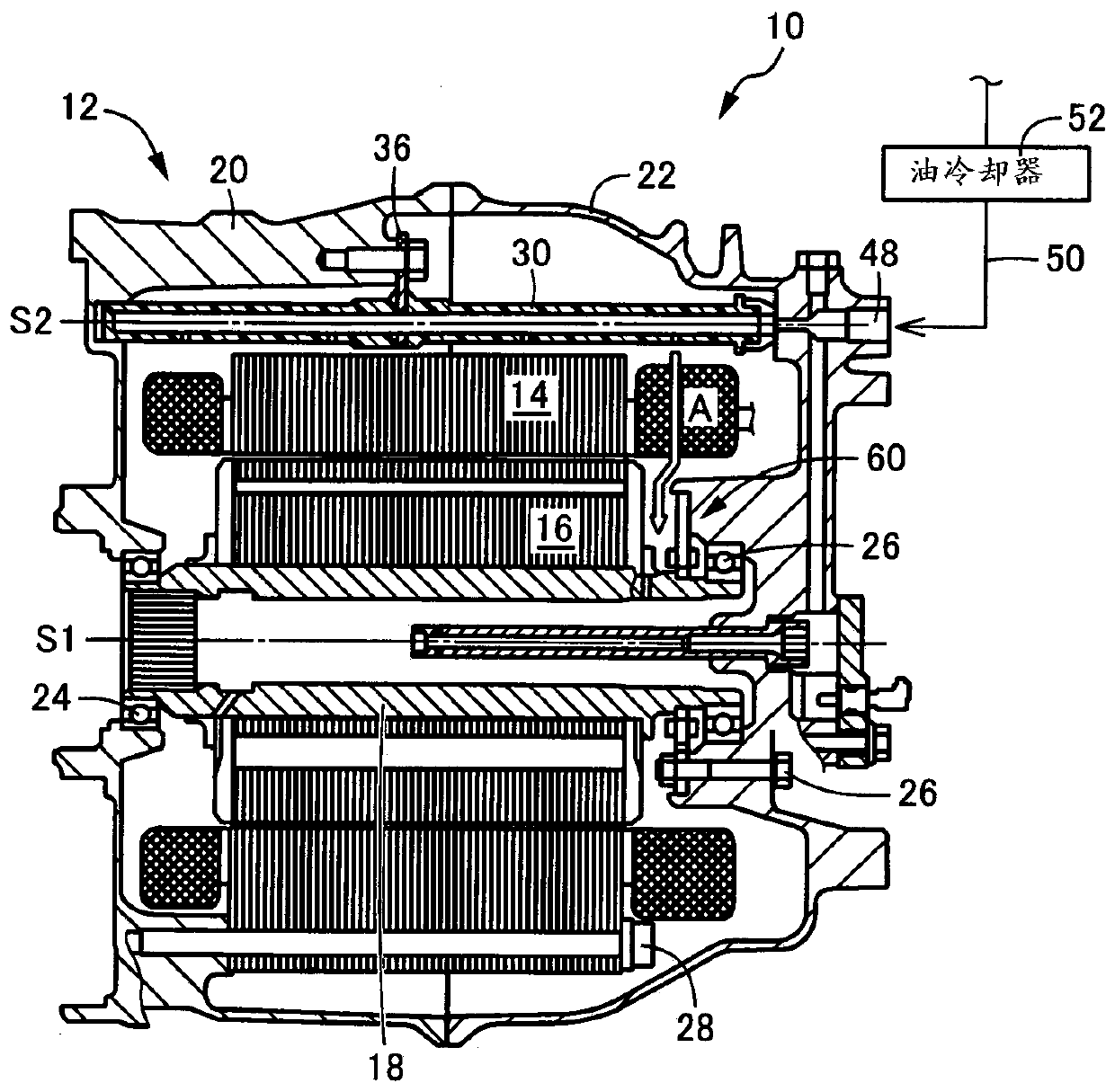
[0031] For example, the present invention is suitably applied to a lubrication structure of a rotary machine (electric motor or motor generator) used as a driving force source of a vehicle, but can also be applied to a rotary machine other than a vehicle. It can also be applied to rotating machines used exclusively as generators. For example, the lubricating oil passage can be constituted only by a fluid passage provided on the wall of the housing, but it is also possible to install a pipe separate from the housing inside the housing and use this pipe as the lubricating oil passage. Lubricating oil cooled by, for example, an oil cooler is supplied to the lubricating oil passage, but the lubricating oil may be supplied without passing through the oil cooler.

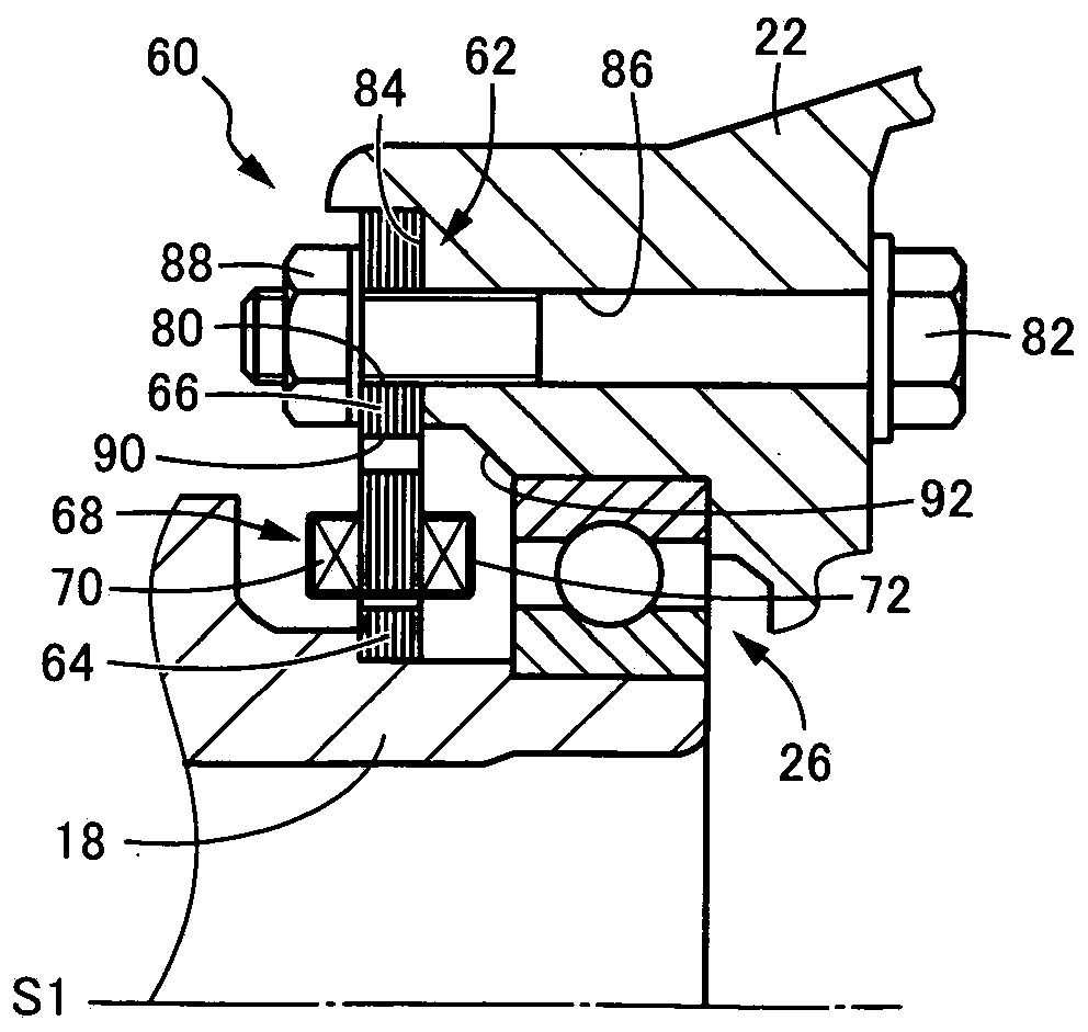
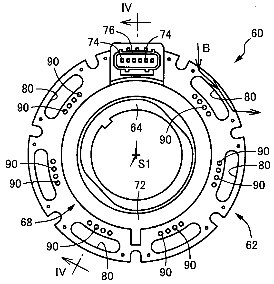
[0032] At least a part of the bearing-side opening of the through-oil hole provided in the resolver stator may be exposed at a portion closer to the inner peripheral side than the fixing portion fixed to the housing, and ...


PUM


Abstract

The invention relates to a rotary machine lubricating structure. In a rotary machine in which a resolver is disposed in a housing, lubricating oil can be appropriately supplied to a bearing on the outer side of the resolver. A through oil hole (90) is provided in the inner peripheral portion of a resolver stator (62) fixed to a mount (84) on the inner surface of a second housing member (22). Therefore, a part of the lubricating oil flowing down from the stator coil part of the rotary machine directly flows into the through oil hole (90) or indirectly flows into the through oil hole (90) due tosplashing or the like caused by rotation of the shaft (18) or the rotor and is supplied to the bearing (26). Since the resolver stator (62) is fixed to the second housing member (22), lubricating oildoes not spatter due to centrifugal force, and a sufficient amount of lubricating oil can be supplied to the bearing (26) and appropriately lubricated by appropriately determining the size, the number, the position, etc. of the through oil holes (90).

Description

technical field [0001] The present invention relates to a lubricating structure for a rotary machine, and more particularly to a lubricating structure for a rotary machine in which a resolver is arranged in a casing. Background technique [0002] There is known a lubricating structure for a rotary machine, which is applied to a rotary machine, the rotary machine having: (a) a cylindrical-shaped stator arranged in a housing concentrically with the center line of the rotary machine and fixed to the casing; (b) a rotor disposed within the casing concentrically with the center line of the rotary machine on the inner peripheral side of the stator; and (c) a shaft aligned with the The rotary machine center line is arranged concentrically and rotates integrally with the rotor, and is supported by the casing via bearings so as to be rotatable around the rotary machine center line, (d) using a The lubricating oil supplied to the stator by the lubricating oil passage cools the stator...

Claims


Application Information

Patent Timeline
Patent Type & Authority Applications(China)
IPC IPC(8): H02K11/225H02K5/16F16C33/66
CPCH02K11/225H02K5/161F16C33/6659F16C2380/26H02K5/203H02K9/19H02K5/20
Inventor 北川胜秀森正树
Owner TOYOTA JIDOSHA KK
Why Eureka
Try Eureka