Optical cable fault positioning method and device based on deep learning, and equipment

A fault location and deep learning technology, applied in machine learning, transmission monitoring/testing/fault measurement systems, instruments, etc., can solve problems such as low precision, high labor costs, and dependence on maintenance personnel, achieving long detection distances and reducing labor costs Effect of cost and equipment consumption, high detection accuracy

Active Publication Date: 2020-08-07
BEIJING UNIV OF POSTS & TELECOMM +3
View PDF7 Cites 9 Cited by
  • Summary
  • Abstract
  • Description
  • Claims
  • Application Information

AI Technical Summary

Problems solved by technology

[0003] In view of this, the purpose of one or more embodiments of this specification is to propose a deep learning-based optical cable fault location method, device and equipment to solve the problem of high labor costs, large equipment consumption, time-consuming and labor-intensive, low precision, and problems in the prior art. Problems causing secondary failures and relying on the work experience of maintenance personnel

Method used


Image

  • Optical cable fault positioning method and device based on deep learning, and equipment
  • Optical cable fault positioning method and device based on deep learning, and equipment
  • Optical cable fault positioning method and device based on deep learning, and equipment

Examples


Embodiment Construction

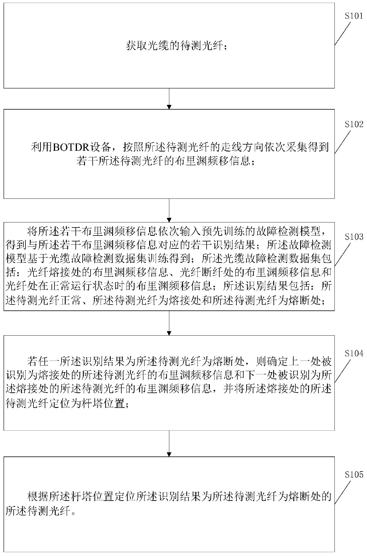
[0044] In order to make the purpose, technical solutions and advantages of the present disclosure clearer, the present disclosure will be further described in detail below in conjunction with specific embodiments and with reference to the accompanying drawings.

[0045] It should be noted that, unless otherwise defined, the technical terms or scientific terms used in one or more embodiments of the present specification shall have ordinary meanings understood by those skilled in the art to which the present disclosure belongs. "First", "second" and similar words used in one or more embodiments of the present specification do not indicate any order, quantity or importance, but are only used to distinguish different components. "Comprising" or "comprising" and similar words mean that the elements or items appearing before the word include the elements or items listed after the word and their equivalents, without excluding other elements or items. Words such as "connected" or "con...


PUM


Abstract

One or more embodiments of the invention provide an optical cable fault positioning method and an optical cable fault positioning device based on deep learning, and equipment. The optical cable faultpositioning method comprises the steps of: acquiring a to-be-detected optical fiber of an optical cable; sequentially acquiring a plurality of pieces of Brillouin frequency shift information of the to-be-detected optical fiber according to the wiring direction of the to-be-detected optical fiber by using BOTDR equipment; sequentially inputting the plurality of pieces of Brillouin frequency shift information into a pre-trained fault detection model to obtain a plurality of identification results corresponding to the plurality of pieces of Brillouin frequency shift information; if the identification result is that the to-be-detected optical fiber is at a fusing position, positioning the position of a tower; and positioning the to-be-detected optical fiber of which the identification result is that the to-be-detected optical fiber is at the fusing position according to the tower position. According to the optical cable fault positioning method and the optical cable fault positioning device, the light operation state information acquired by the BOTDR equipment can be automatically identified, the labor cost is reduced, the optical cable fault can be accurately positioned, and the fault detection model can identify various fault types and position the faults.

Description

technical field [0001] One or more embodiments of this specification relate to the technical field of power grid security, and in particular to a deep learning-based optical cable fault location method, device, and equipment. Background technique [0002] Optical cables are the infrastructure for power transmission in power systems. Real-time detection of optical cables to determine the operating status of optical cables is essential to the safe and stable operation of the power grid. Optical cable fault location is the most critical part of optical cable line maintenance work. In the prior art, optical cable fault location methods include manual pulling, using backscattering method (OTDR) handheld devices under the condition of bending optical fibers, and radio frequency detection. method to measure and locate, OTDR uses OTDR handheld equipment to measure under the condition of quick freezing liquid, etc., using the above methods to find and locate the fault point of the op...

Claims


Application Information

Patent Timeline
Patent Type & Authority Applications(China)
IPC IPC(8): H04B10/07G06K9/62G06N3/04G06N20/00
CPCH04B10/07G06N20/00G06N3/045G06F18/214Y04S10/52
Inventor 赵永利左颖敏刘冬梅张书林丁正阳王颖吴海洋丁士长吴子辰
Owner BEIJING UNIV OF POSTS & TELECOMM
Why Eureka
Try Eureka