Method for establishing airflow structure with partition effect in communication or data center machine room

A technology for data centers and computer rooms, applied in the construction of electrical equipment components, electrical components, cooling/ventilation/heating transformation, etc., can solve the problems of increasing the temperature control energy consumption of the air conditioning system, reducing the temperature control energy consumption of the computer room, etc., Achieve the effect of avoiding the loss of cooling capacity and reducing the energy consumption of temperature control

Inactive Publication Date: 2020-08-07
张礼
View PDF9 Cites 0 Cited by
  • Summary
  • Abstract
  • Description
  • Claims
  • Application Information

AI Technical Summary

Problems solved by technology

In order to reduce the demand for the cooling capacity of the temperature control system in the computer room space, the existing method is to physically partition the idle computer room space on the horizontal plane to reduce the space in the computer room, thereby effectively reducing the cooling capacity demand of the computer room air conditioner. However, in the computer room On the vertical plane, the height of the cabinets that require temperature adjustment only accounts for about half of the height of the equipment room, and the remaining space does not require temperature adjustment. However, the upper part of the equipment room is equipped with dense cable racks, cable channels, etc., which cannot be physically separated , so how to partition the vertical plane of the machine room has become an important problem that needs to be solved urgently
[0003] Due to the air supply and return mode of the air conditioning system in the traditional communication room and the ventilation mode of the communication equipment, the local hot spot of t

Method used


Image

  • Method for establishing airflow structure with partition effect in communication or data center machine room

Examples


Embodiment Construction

[0024] In order to further illustrate the technical means adopted by the present invention and its effects, the following describes in detail in conjunction with preferred embodiments of the present invention and accompanying drawings.

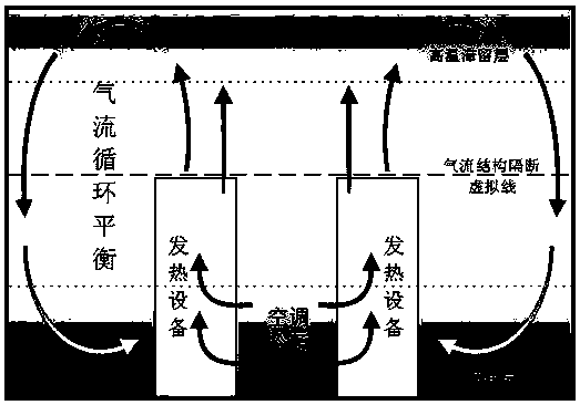
[0025] see figure 1 A method for establishing a partition effect airflow structure in a communication or data center computer room includes the following steps:

[0026] Step 1: Set the relative intervals of the heating equipment in the computer room;

[0027] Step 2: The side or bottom of the heating device is connected to the cold source;

[0028] Step 3: The heat source of the heating device is discharged from the top of the heating device;

[0029] Step 4: The heat source drops after cooling down at the top;

[0030] Step 5: Through steps 1 to 4, air convection is formed in the computer room to cool down the heating equipment.

[0031] Specifically, the heating device is a communication device.

[0032] Specifically, the communication...


PUM


Abstract

The invention discloses a method for establishing an airflow structure with partition effect in a communication or data center machine room. The method comprises the following steps that heating devices in the machine room are oppositely arranged at intervals; the side surfaces or the bottom surfaces of the heating devices are connected with a cold source; a heat source of each heating device is discharged from the top of the heating device; the heat source descends after the top is cooled; air convection is formed in the machine room through the steps one to four, and the heating devices arecooled. According to the invention, buoyancy and equipment exhaust air are used as power sources to form a ventilation mode with air natural convection jet flow as main characteristics; when the temperature of the indoor heating device is higher than the surrounding indoor temperature and forms a heat source, indoor air is subjected to natural convection heat exchange along the periphery of the heat source, the heat source surrounding air after heat exchange naturally rises under the action of buoyancy and equipment exhaust air, so that the heat source surrounding air forms natural convectionjet flow from bottom to top and rises to the indoor top together with the heat source surrounding air, and local hot spots of the machine room rise to the top space of the machine room.

Description

technical field [0001] The invention relates to a method for establishing a partition effect air flow structure in a communication or data center computer room, in particular to the field of temperature control in a communication computer room and a data center computer room. Background technique [0002] At present, with the continuous expansion of the communication network and the rapid increase in the number of servers in the data center, the power consumption of the computer room has become an increasingly important cost, of which the power consumption for the temperature control system accounts for a considerable proportion. In order to reduce the demand for the cooling capacity of the temperature control system in the computer room space, the existing method is to physically partition the idle computer room space on the horizontal plane to reduce the space in the computer room, thereby effectively reducing the cooling capacity demand of the computer room air conditioner...

Claims


Application Information

Patent Timeline
IPC IPC(8): H05K7/20
CPCH05K7/20709
Inventor 张礼
Owner 张礼
Why Eureka
Try Eureka