

Equipment for removing cement on surfaces of steel pipes of scaffold for building
A technology for cleaning equipment and construction. It is applied in metal processing equipment, grinding/polishing equipment, grinding racks, etc. It can solve the problems of large consumption, slow cement speed, and poor effect, so as to improve the cleaning effect and improve the The effect of work efficiency
- Summary
- Abstract
- Description
- Claims
- Application Information
AI Technical Summary
Problems solved by technology
Method used
Image

Examples
Embodiment 1
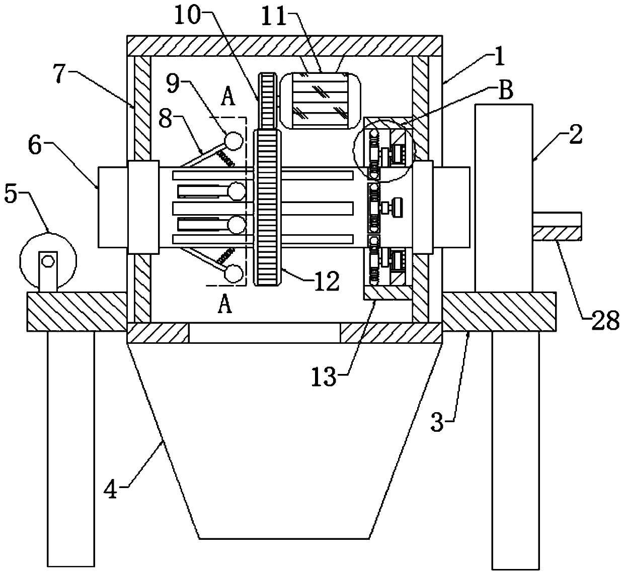
[0024] A kind of equipment for cleaning the cement on the outer surface of steel pipes for construction, including a horizontal plate 3, a casing 1 is fixedly connected between the upper and lower ends of the horizontal plate 3 through a rectangular opening, and the inner edges of the left and right ends of the casing 1 are fixed A sealing plate 7 is connected, and the opposite sides of the two sealing plates 7 are rotatably connected to a horizontal tube 6 through the first rolling bearing, and both ends of the horizontal tube 6 pass through the first rolling bearing and extend to the outside of the casing 1. An annular block 13 is provided inside, the inner side of the annular block 13 is socketed with the pipe wall of the horizontal pipe 6, one side of the annular block 13 is fixedly connected with one side of one of the sealing plates 7, and the horizontal pipe 6 is located in the pipe in the annular block 13 A cleaning mechanism is connected inside the wall, and a pluralit...
Embodiment 2
[0026] Embodiment 2: the difference based on Embodiment 1 is;
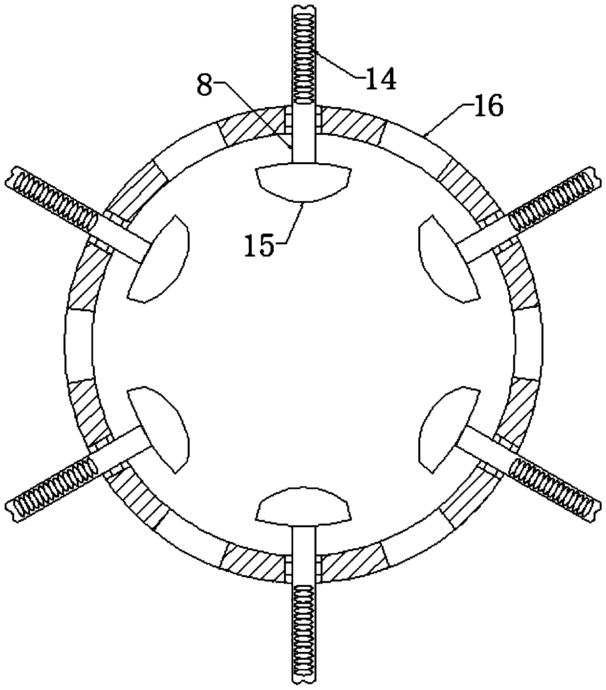
[0027]The cleaning mechanism includes a plurality of installation blocks 27 evenly fixed on the wall of the horizontal tube 6, one side of the plurality of installation blocks 27 is rotatably connected with a rotating shaft through the first sealed bearing, and one end of the rotating shaft passes through the first sealed bearing and is fixed. A second gear 25 is connected, and a disk 24 is fixedly connected to the other end of the rotating shaft. Two first springs 23 are symmetrically fixedly connected to the edge of the disk 24, and the ends of the two first springs 23 away from the disk 24 are fixedly connected. There is a ball 22, and a rectangular through hole is opened on the tube wall of the horizontal tube 6, and the rectangular through hole is movably socketed with the ball 22 on one of the first springs 23, and the inner side of the annular block 13 is fixedly connected with an internal ring gear 26, The...
Embodiment 3
[0029] Embodiment 3: the difference based on embodiment 1 is;
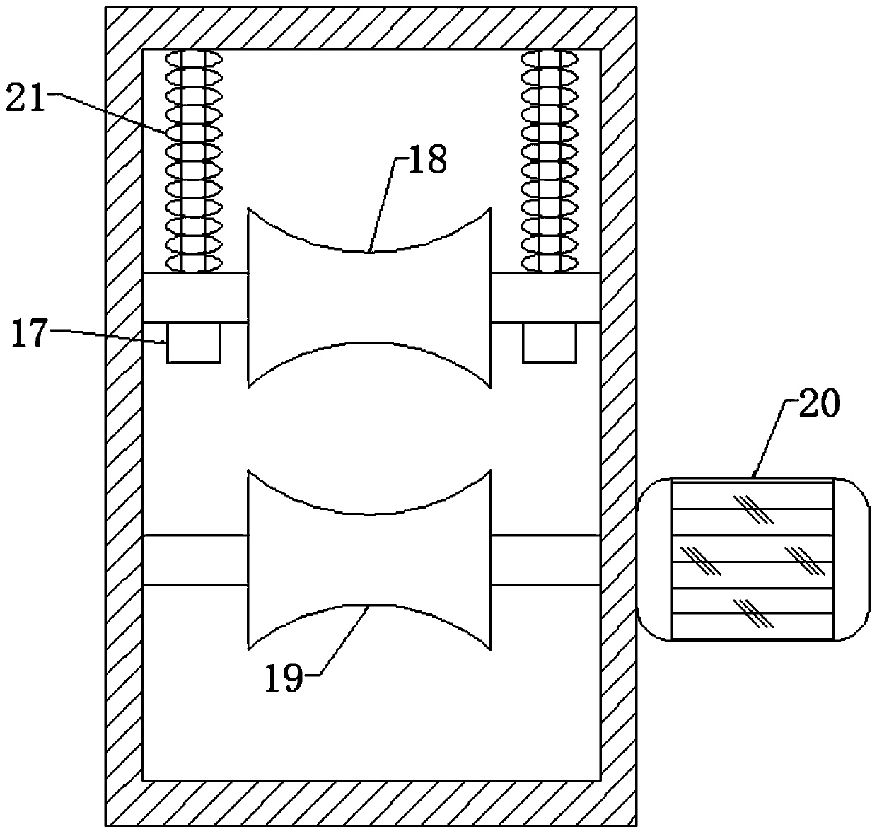
[0030] The transmission mechanism includes a transmission roller 19 arranged in the rectangular frame 2, and the opposite sides of the transmission roller 19 are fixedly connected with a transmission shaft at the same axis. The inner wall of the rectangular frame 2 is rotationally connected, one side of the rectangular frame 2 is fixedly connected with a second motor 20, the output end of the second motor 20 passes through the second rolling bearing and is fixedly connected with one end of the drive shaft, and the inner wall of the upper end of the rectangular frame 2 is symmetrically fixedly connected with Two inverted T-shaped rods 17, the rod walls of the two T-shaped rods 17 are provided with connecting shafts, the shaft walls of the connected shafts are slidingly socketed with the rod walls of the T-shaped rods 17 through positioning holes, and the rectangular frame 2 is provided with There is a pressure roll...
PUM
 Abstract
Description
Claims
Application Information